Click the blue text to follow us

1. Simple Control Applications of Microcontrollers
1. Clock Timing
(1) Clock Timing Setup
Using the timer/counter of the 80C51 to achieve clock timing is a great application topic. The explanation is as follows:
-
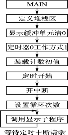
Calculate the initial count value.
-
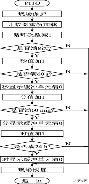
Use interrupt mode, that is, accumulate the number of timer overflows through the interrupt service routine, and when it reaches 8 times, it indicates one second timing.
-
Implement timing from seconds to minutes and from minutes to hours through value accumulation and comparison in the program.
-
Set up a clock display buffer.
(2) Program Flow
① Main Program MAIN
② Interrupt Service Routine PIT0
③ Increment Subroutine DAAD1
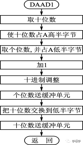
The increment operation includes the following three items:
-
Merging numbers. Since each LED display corresponds to an 8-bit buffer unit, the time value represented by two BCD codes occupies one buffer unit each and only occupies its low 4 bits. Therefore, before the increment operation, the values stored in the two buffer units need to be merged to form one byte, and then the increment operation can be performed. This is also called “merging bytes”.
-
Decimal adjustment. After incrementing, decimal adjustment is required.
-
Fraction. The incremented time value is split back into two bytes and sent back to their respective buffer units.
2. Digital Thermistor Thermometer
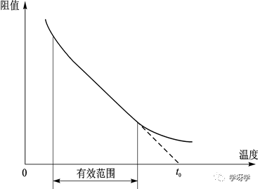
(1) Thermistor Temperature Conversion Principle
Where:
-
t is the measured temperature
-
t0 is a temperature parameter related to the thermistor characteristics.
-
K is a coefficient related to the thermistor characteristics.
-
VT is the voltage across the thermistor.
(2) Basic Circuit
Assuming the use of ADC0809 for A/D conversion. The circuit connection is shown in the figure below
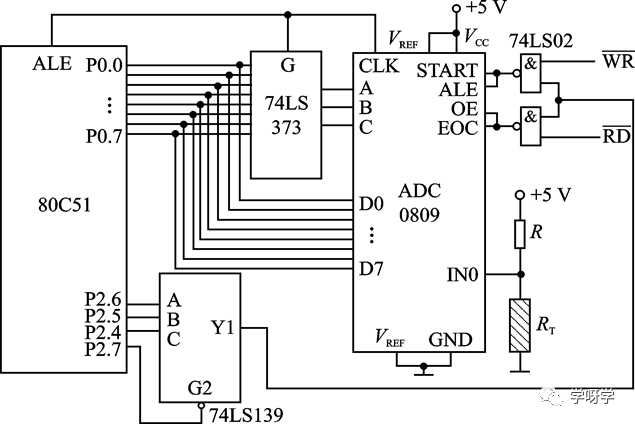
Digital Thermistor Thermometer
(3) Program Design
1) Temperature Calculation Program
COMP: MOVB, #0XXH ; Send the expanded K value of 256 to B
MULAB; 256×K×VT
MOVA, #0YYH ; Send T0 value to A, discard the low 8 bits of the product
CLRC ; Clear carry bit
SUBBA, B; t0-K×VT
CJNEA, #0AH, COMP1
COMP1: JNC COMP4 ; If temperature is below 10℃, display F
CJNEA, #97H, COMP2
COMP2: JC COMP3 ; If temperature is below 151℃, then branch
COMP4: MOV 27H, #0FH ; Exceeding effective temperature range, display F
MOV28H, #0FH
MOV29H, #0FH
MOV2AH, #0FH
MOV2BH, #0FH
MOV2CH, #0FH
ACALLDISP ; Call display subroutine
COMP3: RET
2) Temperature Value Conversion to Decimal Program
MOVR1, #00H
MOVR2, #00H
CLRC
CHAN: SUBBA, #64H ; Subtract 100
JCCHAN1 ; If not enough to subtract, then branch
INCR1 ; Enough to subtract, effective position 1
AJMPCHAN2
CHAN1: ADDA, #64H; Restore coefficient
CHAN2: SUBBA, #0AH ; Subtract 10
JCCHAN3 ; If not enough to subtract, then branch
INCR2 ; Enough to subtract, increment the tens digit by 1
AJMPCHAN2; Repeat subtracting 10
CHAN3: ADDA, #0AH; Restore the unit digit
MOV27H, #0AH
MOV28H, #0DH
MOV29H, #10H
MOV2AH, R1
MOV2BH, R2
MOV2CH, A
RET
2. Development of Microcontroller Applications
The application of microcontrollers deepens the integration of computer technology and automatic control technology, fundamentally changing the traditional design ideas and methods of control systems. Functions that previously had to be implemented by analog or digital circuits can now be realized using microcontrollers through software (programming). This technology of replacing hardware with software to improve system performance is called microcontrol technology.
The microcontroller control system realized through microcontrol technology belongs to embedded systems, as the microcontroller is part of the controlled system and serves as the main control unit of the system.
As an embedded system, the key point is to integrate software and hardware, meaning that both the operating system and application programs are “burned” into the program memory (software hardening). Embedded systems are generally more complex and often require an operating system for management, which is known as embedded operating systems.
People have begun to study how to connect microcontroller systems to the Internet to transmit measurement and control information via the Internet, thus achieving the long-sought dream of scientists for remote automatic detection and control. Therefore, how to enable microcontrollers to access the Internet is what is known as microcontroller Internet technology.
-
Establishing a home network environment through microcontroller Internet technology. -
Microcontroller Internet technology is also significant for unattended measurement and control work.
3. Microcontroller Development Systems
Simulation is the process or method of implementing the function of one computer or program in another computer or program, while a simulator is the hardware device and software that achieve this function.
A simulator is a product of the integration of computer technology, simulation technology, and logic analysis technology, consisting of a basic computer system plus some simulation modules and software. Many current microcontroller simulators support not only assembly language development but also C language development, with standard software packages available for direct invocation.
Currently, microcontroller system development is conducted using online simulation methods, and devices that can achieve online simulation are called online simulators ICE (In-Circuit Emulator), and the simulation method using ICE to replace the CPU of the developed system is called online simulation.
Simulators have functions such as system design, system testing, fault online analysis, and microcontroller system dissection for a full range of microcontrollers. In use, it can run programs with the same timing as the user’s microcontroller, set breakpoints as needed, accept commands at any time, and conduct comprehensive testing and complete data transmission for the user system. A simulator should also have rich development software.
An important criterion for evaluating the quality of a simulator is its transparency.
Simulators can also simulate debugging of the user’s system in a simulated field environment.

Long press the image to follow
Discover more exciting content
WeChat ID: Mechanical-knowledge