1. Overview
L2CAP: Logical Link Control and Adaptation Layer Protocol
The structure and position of L2CAP in the protocol stack are shown in the figure below:
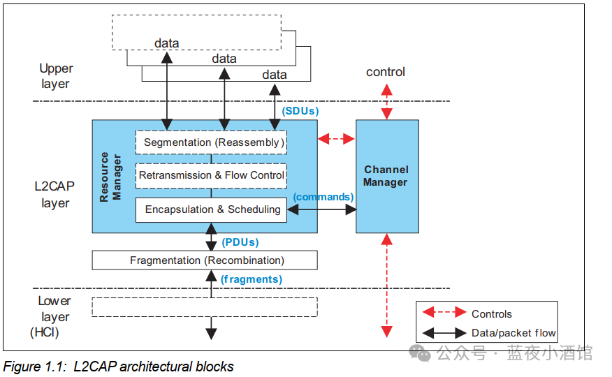
1.1 Channel Manager
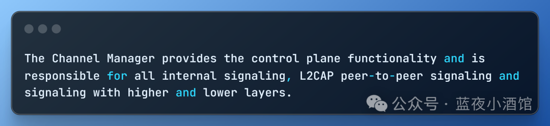
The Channel Manager provides control plane functionality and is responsible for all internal signaling, L2CAP peer signaling, and signaling interactions with upper and lower layers.
1.1.1 Internal Signaling
The L2CAP module coordinates communication between internal components as follows:
-
Manage channel state machine transitions
-
Coordinate resource allocation (resource allocation in Zephyr is implemented through net_buf_pool for buffer pre-allocation strategy)
-
Handle timer events (e.g., connection timeout L2CAP_CONN_TIMEOUT)
Zephyr implementation:
For example, the state machine example in Zephyr:
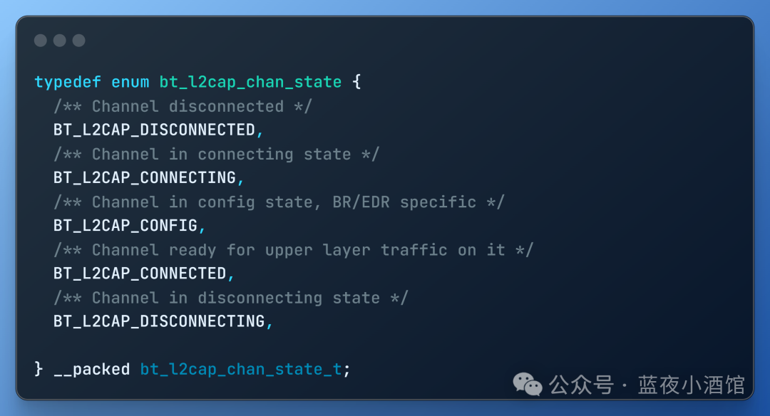
Set state machine transitions using bt_l2cap_chan_set_state;
Set connection timeout using l2cap_chan_send_req(&ch->chan, buf, L2CAP_CONN_TIMEOUT)
1.1.2 L2CAP Peer-to-Peer Signaling
Interact with the L2CAP layer of the remote device through signaling channels
Dynamic channel establishment/release
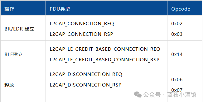
Parameter negotiation
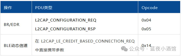
Flow control credit exchange
BLE credit flow control:L2CAP_FLOW_CONTROL_CREDIT_IND (Opcode 0x16)
1.1.3 Signaling with Higher/Lower Layers
L2CAP interacts vertically with other layers of the protocol stack
-
L2CAP → Upper layer protocols (callback interfaces)
-
L2CAP ⇄ HCI layer (ACL data/HCI events)
-
Upper layer protocols → L2CAP (API calls)
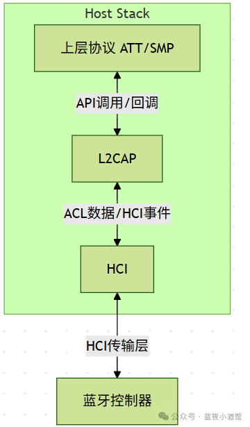
In the Zephyr Bluetooth stack, the L2CAP channel manager is not an independent module or data structure, but a logical abstraction of cross-file collaborative functionality.
1.2 Resource Manager
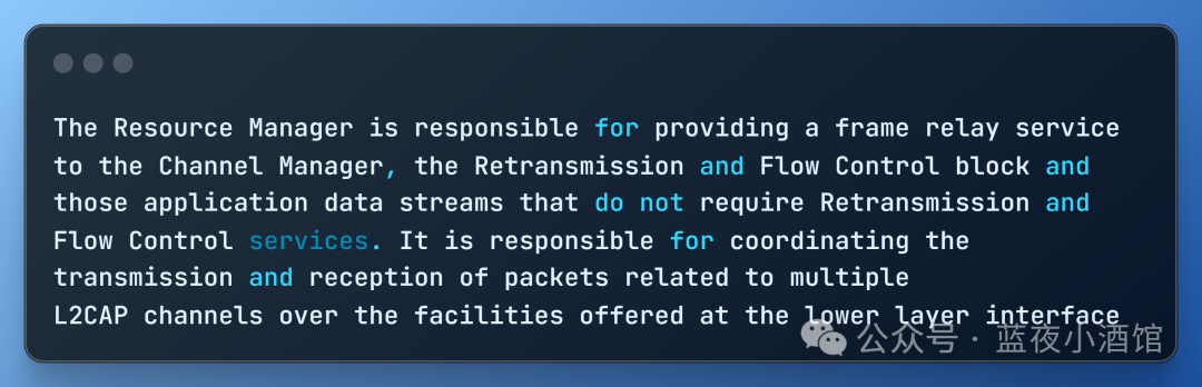
The main responsibility of the Resource Manager is to efficiently and fairly coordinate and manage access to limited transmission resources for multiple concurrent L2CAP logical channels, ensuring that packets from different channels can be sent and received in an orderly and timely manner, and providing basic frame relay services for specific entities.
1.2.1 Providing Basic Transport Services (Frame Relay)
- Service targets: Channel Manager, Retransmission Flow Control Module (RFCB), application data streams that do not require RFCB services (e.g., low-latency audio).
- What it does:Make every effort to deliver data frames (PDU),not responsible forretransmission, flow control, large packet segmentation and reassembly (SAR).
- Significance:RFCB builds reliable transmission on top of it; low-latency data streams can bypass RFCB to reduce overhead.
1.2.2 Sending Coordination (Scheduling)
Only one packet can be sent at a time at the lower layer, but multiple channels need to send data simultaneously.
The RM solves:
Receiving send requests from each channel.
-
Scheduling: Decide which packet from which channel to send next based on priority, fairness, QoS requirements, and resource status.
-
Order: Ensure that packets within the same channel are sent in order.
-
Submission: Submit the selected packet to the lower layer (e.g., HCI) for sending.
1.2.3 Receiving Coordination (Dispatching)
Packets coming from the lower layer belong to different channels and need to be correctly dispatched.
The RM solves:
Receiving lower layer data packets.
Demultiplexing: Identify which channel the packet belongs to based on the target channel ID (DCID) in the packet header.
Dispatching: Deliver the packet to the corresponding processing entity:
- Channel with RFCB enabled -> hand over to RFCB.
- Channel/application stream without RFCB enabled -> direct delivery.
- Control signaling -> hand over to the Channel Manager.
Order: Ensure that packets within the same channel are delivered to the upper layer in order.
2. Functions of L2CAP
2.1 Protocol Multiplexing
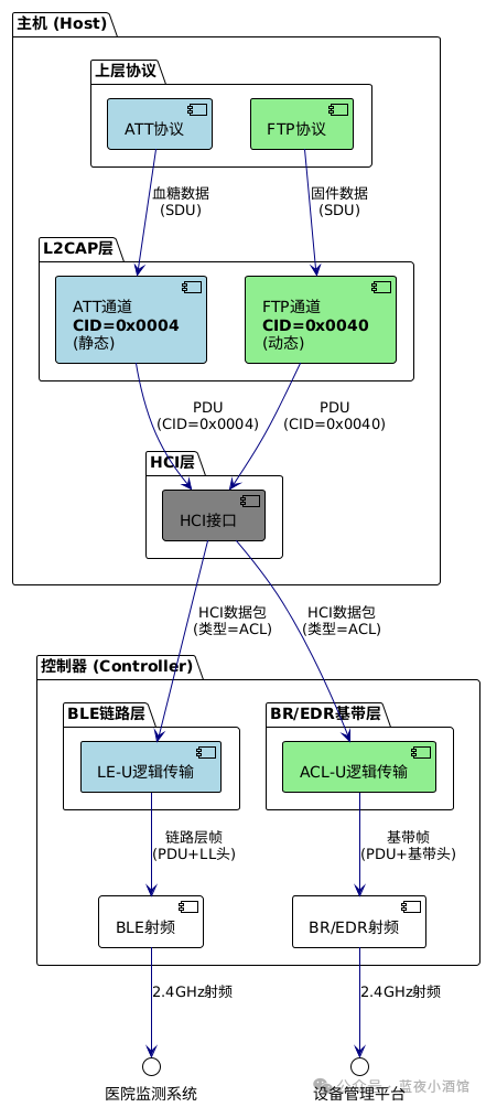
Different protocol data streams are distinguished by CID (Channel Identifier)
For example, medical devices transmitting simultaneously:
- CID=0x0004 → BLE blood glucose data (ATT protocol)
- CID=0x0040 → Firmware upgrade (FTP protocol)
The process is shown in the figure below:
2.2 Segmentation and Reassembly (SAR)
The sender automatically splits data packets that exceed the physical layer single frame capacity into blocks suitable for physical layer transmission, and the receiver reassembles them into the original data based on protocol header information, making the entire process completely transparent to upper layer applications.
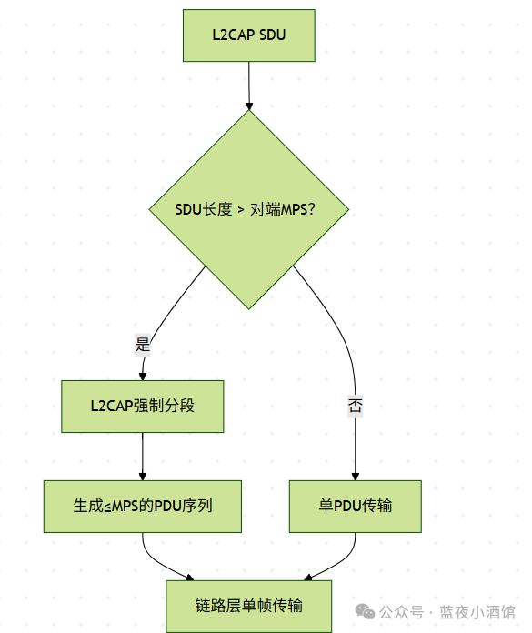
1) BLE Dynamic Channel (LE Credit Based Flow Control)
Trigger condition: When the L2CAP SDU length > the MPS (Max PDU Size) declared by the peer, the L2CAP layer must segment.
MPS definition: MPS is the maximum capacity declared by the receiver for a single frame (including L2CAP header).
Connection establishment mandatory check: If the peer MSP ≤ local link layer MTU, otherwise reject the connection.
After segmentation guarantee: Each PDU ≤ MPS ≤ link layer MTU → no fragmentation required at the link layer.
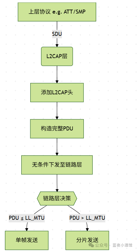
2) BLE Static Channel (ATT/SMP)
The L2CAP layer does not perform segmentation.
In static channels, the L2CAP layer does not perform segmentation on SDUs (Service Data Units).
Regardless of the length of the SDU (1 byte or 1000 bytes), the L2CAP layer directly packages it into a PDU and hands it to the link layer.
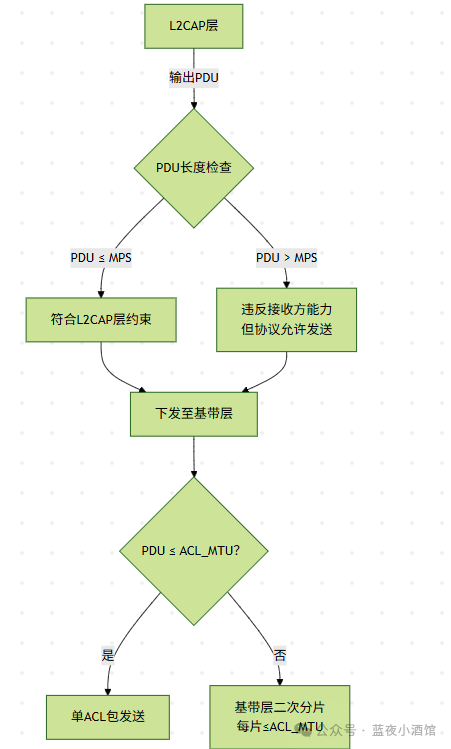
3) Classic Bluetooth Static Channel
The L2CAP layer does not fragment PDUs, always outputting complete protocol data units.
MPS only represents the processing capability of the receiving L2CAP layer, and does not trigger any fragmentation behavior.
The baseband layer (via HCI) decides physical fragmentation based on ACL_MTU:
- PDU ≤ ACL_MTU → single packet transmission
- PDU > ACL_MTU → forced fragmentation (regardless of MPS)
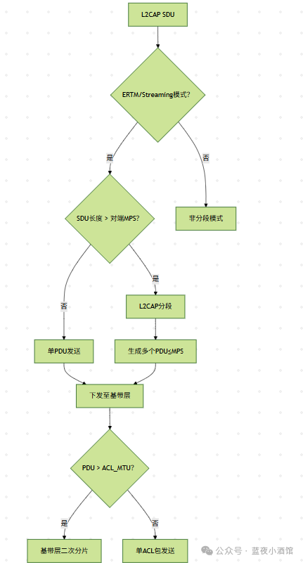
4) Traditional Bluetooth Dynamic Channel
Mode dependency: Only enabled when using ERTM (Enhanced Retransmission Mode) or Streaming Mode.
Segmentation trigger: When the SDU length > the peer MPS, the L2CAP layer segments.
Even if L2CAP segmentation meets MPS, if L2CAP PDU > baseband ACL packet length, the baseband layer must perform secondary fragmentation.
2.3 Channel Flow Control
Bluetooth device resources are severely asymmetric (e.g., headphones with only 2KB RAM, while a phone has 200MB), requiring prevention of high-performance devices from overwhelming the low-performance device’s receive buffer. Therefore, a flow control mechanism has been introduced.
Flow control: A protective mechanism to prevent the sender’s data from overwhelming the receiver’s buffer, which is a resource management led by the receiver;
-
Basic mode without flow control → relies solely on timeout retransmission → high packet loss rate
-
Traditional ERTM sliding window is complex → excessive resource consumption (not suitable for IoT devices)
-
Credit system born: a lightweight solution tailored for BLE
Credit value: A PDU sending license granted by the receiver (1 credit = 1 PDU)
MPS: Maximum Protocol Data Unit (upper limit of single PDU length), mandatory constraint: PDU ≤ MPS ≤ LL_MTU
Specific example: For instance, when a phone sends data to a bracelet, the initial credit value is 5.
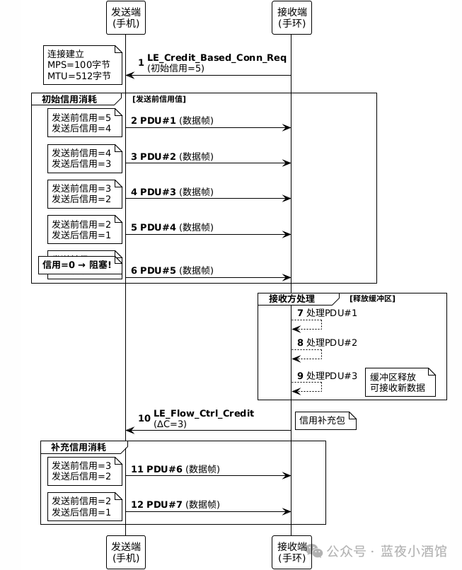
1) The receiving end (bracelet) sends an L2CAP connection request to the sending end (phone), which includes the initial credit value of 5.
2) The sending end sends 5 PDUs (PDU1 to PDU5), reducing the credit value by 1 for each PDU sent, and after sending PDU5, the credit value becomes 0, triggering a block.
3) The receiving end processes 3 PDUs, freeing up the buffer.
4) The receiving end sends a credit packet to the sending end, replenishing the credit value by 3 (ΔC=3).
5) The sending end continues to send PDU6 and PDU7, with the credit value decreasing from 3 to 2 and then to 1.
2.4 Retransmission Mechanism
Fix lost L2CAP data packets (PDU) during transmission to ensure reliable data transmission.
Bluetooth retransmission can occur at the physical layer, application layer, and L2CAP layer (only in traditional Bluetooth ERTM mode).
This section briefly introduces the L2CAP layer retransmission (only in traditional Bluetooth ERTM mode).
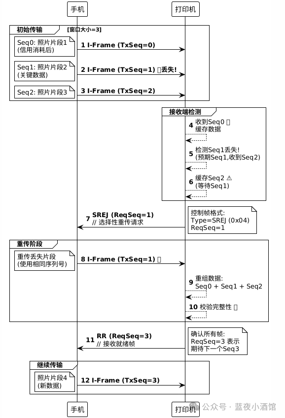
Trigger condition: The receiver detects discontinuity in the PDU sequence number.
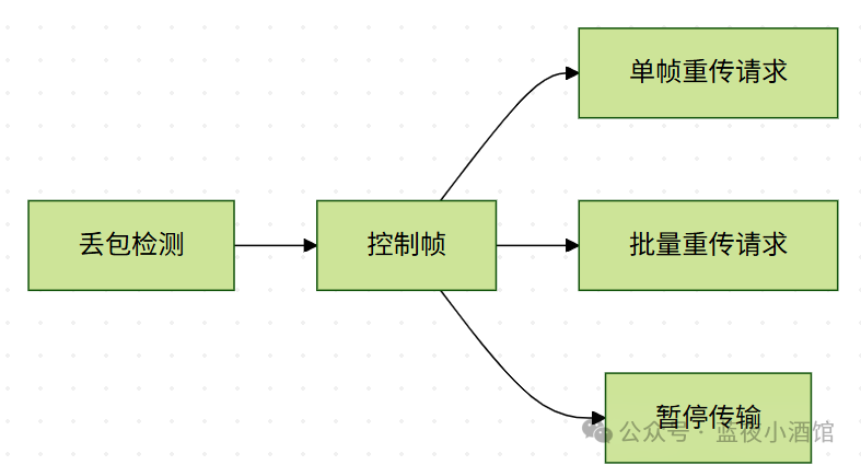
Classic Bluetooth ERTM selective retransmission (SREJ) process:
2.5 Fragmentation and Reassembly
In section 2.2 Segmentation and Reassembly (SAR), the concept of fragmentation and grouping has already been implicitly introduced. Here we will delve deeper into it: Fragmentation and reassembly may occur at the layers shown in the figure below:
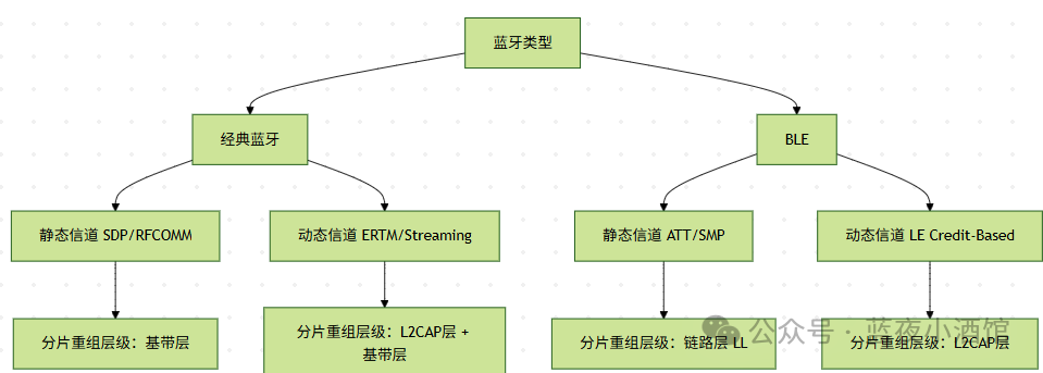
The essential definition of fragmentation/recombination: A PDU length adaptation mechanism at the lower layer of the Bluetooth protocol stack (baseband layer/link layer) to solve the incompatibility problem between upper layer protocol data units (PDU) and the maximum effective payload length (Max Payload Length) of the physical layer. Its core mechanism is as follows:
1) Trigger condition: Activated when the L2CAP PDU length > physical layer MTU.
- BR/EDR: PDU > ACL_MTU
- BLE: PDU > LL_MTU (27~251)
2) Operational level::
- BR/EDR: Baseband layer
- BLE: Link layer
3) Processing principles::
- Fragmentation: Split a single PDU into N physical frames ≤ MTU
- Reassembly: The receiving end sequentially stitches the physical frames to restore the original PDU
4) Protocol independence: Fragmentation and reassembly are the binary porters in the Bluetooth protocol stack
- Does not parse L2CAP headers
- Does not perceive channel CID
- Not constrained by flow control
3. L2CAP Scope Definition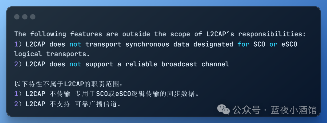
3.1 Does not transmit SCO/eSCO synchronous data
The fundamental reason: architectural layer isolation
SCO (Synchronous Connection-Oriented): Used for ≤64 Kbps raw audio streams (e.g., voice calls), data is transmitted directly at the baseband layer (Link Layer)
Transmission path:
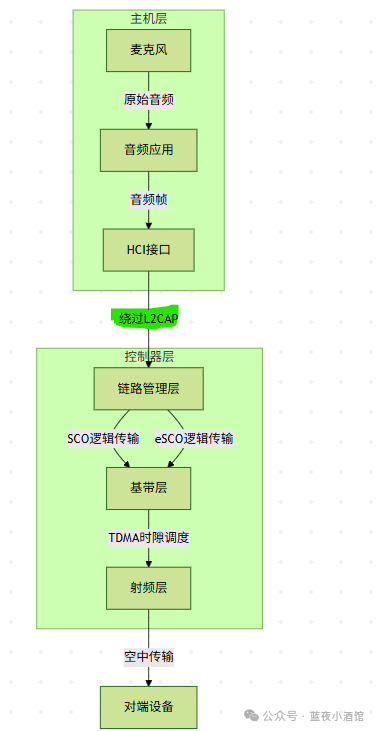 Audio source: Microphone → Collect PCM audio (typical format: 16-bit/8kHz)Audio application: (e.g., HFP) → Perform encoding (CVSD/mSBC)
HCI pass-through: Encoded audio frames are injected directly into HCI (bypassing L2CAP), using dedicated channels:
-
HCI_SCO_Data_Packet
-
HCI_eSCO_Data_Packet
eSCO (Extended SCO)
Enhanced version of SCO, supports retransmission of limited audio frames (e.g., wideband voice) still managed exclusively by the controller
The asynchronous nature of L2CAP
L2CAP is designed as anasynchronous packet-switched protocol, whosebuffer-retransmission mechanism can disrupt the timing requirements of synchronous streams, leading to audio jitter.
Typical scenario: Voice data of HFP (Hands-Free Profile) is transmitted via eSCO logical transport (non-L2CAP channel) directly to the baseband
3.2 Does not support reliable broadcast channels
The essential flaw of broadcasting:
-
Bluetooth broadcasting (Advertising) isconnectionless and unacknowledged transmission
-
The receiving devicecannot provide feedbackACK/NACK, making reliability assurance impossible
L2CAP’s reliable transmission (e.g., RFCB module) requires:
-
Point-to-point connection (identified by CID)
-
Credit flow control mechanism (Credit-Based Flow Control)
-
Error detection and retransmission (Automatic Repeat reQuest ARQ)
All of these mechanismsare mutually exclusive with the broadcast architecture, so L2CAP does not support reliable broadcast channels.
ConclusionL2CAP is based on channel multiplexing and resource coordination, allowing multiple applications (such as file transfer, device discovery, audio control) to share a Bluetooth connection simultaneously through flexible data channel allocation. It utilizes segmentation and reassembly capabilities to break down large data from upper layer applications into smaller chunks that can be processed by the lower layer for transmission, and perfectly restores them at the receiving end. Additionally, it employs mechanisms such as credit flow control and automatic retransmission to ensure reliable delivery of data such as file transfers while also accommodating real-time applications like audio streams, ensuring smoothness, ultimately transforming complex wireless signal transmission into a reliable and stable data service for upper layer applications.