A few days ago, we published a monitoring networking solution, and some friends commented, hoping we would produce a case solution for the all-optical network. In fact, we have previously summarized the technical content regarding all-optical networks. In recent years, all-optical networks have indeed become quite popular, being applied in hotels, office buildings, schools, and parks. Many project managers in our weak current VIP technology group are also working on related projects.

In this issue, we will use this all-optical network architecture solution to gain a detailed understanding of all-optical networks.
1. Overall Framework Design
The overall network solution design is based on principles of high performance, high reliability, high security, wired and wireless integration, and a unified network management system, while also considering the advancement and maturity of technology, adopting a modular design approach.
The entire network design adopts a hierarchical and modular design concept, deploying network devices according to the access layer, core layer, and exit layer. An important feature of the entire network is that optical links are used between switches to ensure link-level reliability.
2. Networking Solution
Choose high-capacity optical access devices for OLT, and select terminals for ONU based on actual application scenarios. The splitter can range from 1:2 to 1:64.
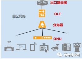
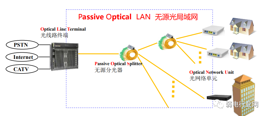
The networking schematic is as follows:
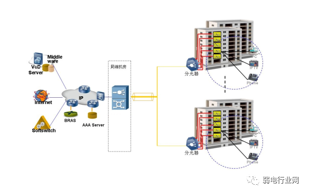
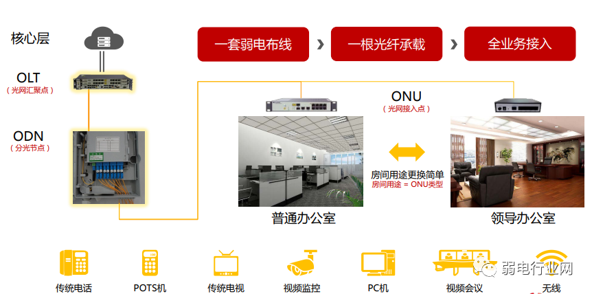
As an optical access device application, the OLT device for EPON/GPON connects to broadband IP metropolitan network devices like BRAS, LSW, or Router, demodulating different types of services from the terminal into Ethernet services, providing users with high-speed internet access, IPTV, and VoIP services.
The service process is shown in the diagram below:
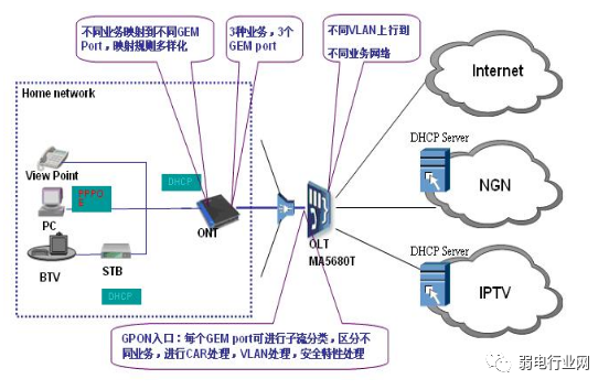
For PC users, the IP address is obtained using PPPoE, while VoIP and STB users obtain the IP address using DHCP. Different mapping rules are applied on the ONT according to the type of service, mapping the services to different GEM ports for uploading, and then classifying the flow based on different services at the OLT side, performing packet remarking and VLAN switching, connecting to the upper-level network via the uplink port.
EPON/GPON terminals connect PCs, set-top boxes, and phones in shops and offices.
3. Components of All-Optical Network Construction
All-optical network structure:
This complete all-optical network consists of OLT, ODN, ONU, routers, terminals, etc. Each device has its important role, particularly the three key devices: OLT, ODN, and ONU. Let’s take a look at their functions.
1. OLT:
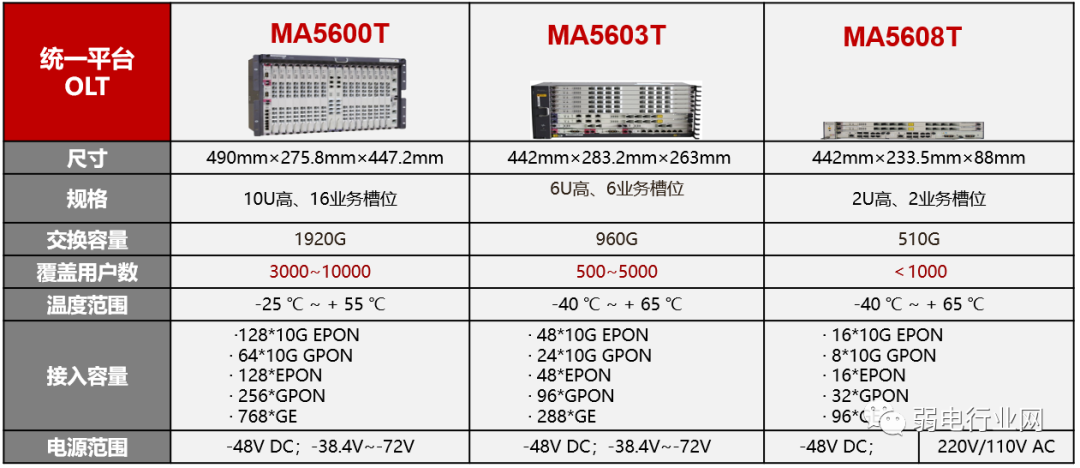
The Optical Line Terminal connects to the trunk line’s terminal device. The OLT is the core component of the optical access network, equivalent to the switch or router in traditional communication networks, and serves as a multi-service platform. It is generally placed at the central office, providing fiber interfaces for a passive optical network facing users.
The main functions it performs include connecting to the upper-level network and completing the uplink access of the PON network. It connects to user-end devices ONU through the ODN network (composed of optical fibers and passive splitters) and implements control, management, and distance measurement functions for user-end devices ONU.
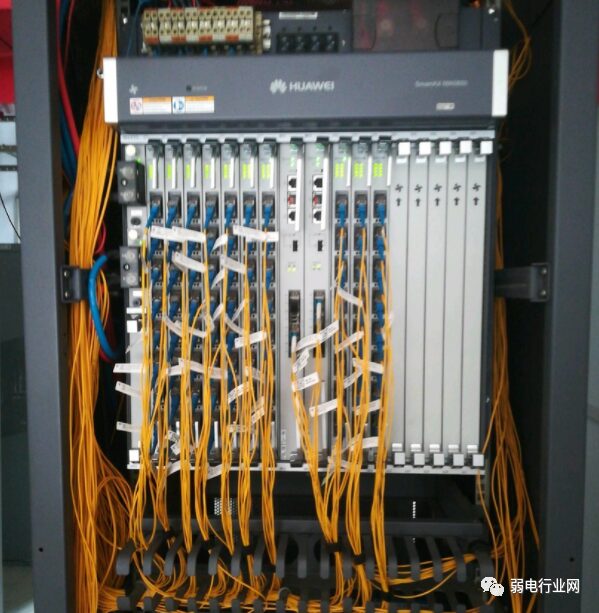
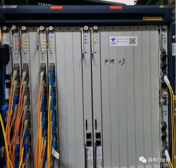
As we can see, Huawei’s OLT devices have very clear parameters, and the appropriate device is selected based on coverage requirements.
OLT is generally located in the machine room, connected to the ODF cabinet.
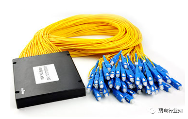
2. ODN
Optical Distribution Network: A fiber optic network based on PON equipment, providing optical transmission channels between the OLT and ONU. We generally use splitters, which consist of incident and outgoing slits, mirrors, and dispersion elements, to separate the required resonant absorption lines. The splitter is a component for constructing the PON network, connecting the OLT and ONU. Its function is to distribute downstream data and concentrate upstream data. The splitter has one upstream optical interface and several downstream optical interfaces. Common splitter ratios include 1:2, 1:4, 1:8, 1:16, 1:32, and 1:64.
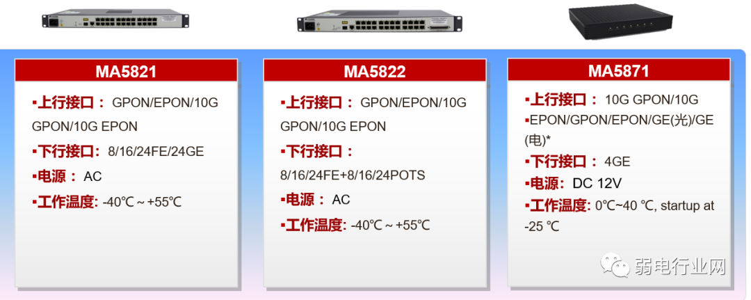
3. ONU Introduction
The Optical Network Unit, ONU is divided into active optical network units and passive optical network units. The device containing an optical receiver, upstream optical transmitter, and multiple bridging amplifiers for network monitoring is called an optical node. PON uses a single fiber connection to the OLT, then the OLT connects to the ONU. The ONU provides data, IPTV, voice, etc., aiming to carry as many terminal users as possible without affecting communication efficiency and quality, thereby improving network utilization and reducing user costs.
Huawei’s related ONU equipment:
We can see the application of ONU, connecting the ODN and OLT, downloading for terminal users:
3. Comparison of Splitting Methods
When splitters are cascaded step by step, they need to occupy the downstream port of the upper-level splitter for cascading, increasing the splitting ratio and the number of joints, thereby reducing the ODN coverage range. At the same time, as the number of cascades increases, the complexity of the ODN network, construction difficulty, and fault points increase. Therefore, it is recommended to adopt a two-level cascading approach, and in principle, it should not exceed three levels.
4. All-Optical Network Wireless WIFI Network Solution
All-optical networks are applied in shopping malls or hotels. Entering commercial areas allows customers to self-join wireless network signals by sending verification codes to customers, enabling merchants, tourists, owners, and tenants to connect to the internal wireless network of the building. Property management companies or mall operators can send investment, leasing, and promotional information to potential users based on the overall situation of the mall and office (investment promotion activities, mall promotional activities).
Each zone’s wireless network is connected to the equipment room, with wireless access controllers placed between devices. The controller provides high-speed adaptive Ethernet ports of 100M/1000M, connecting to the backbone network and the managed area. POE switches are placed in the distribution cabinets of each zone, directly connecting to the AP placement on each floor using category 6 cables. High-power APs following the general 802.11g standard cover the wireless network on each floor, enabling users to achieve wireless broadband internet access.
APs are placed in public areas of buildings for wireless network coverage. APs are installed on ceilings, connecting and transmitting through weak current bridge racks from distribution cabinets, configuring a relative number of POE switches in the distribution cabinets.
This project sets up a total of 80 AP points.
Each floor’s AP points are connected by a 24-port POE switch located in the weak current vertical shaft, providing power. Switches connect to ONU devices, and AP points are usually aggregated every 2-3 floors.
The AC controller is set in the basement’s weak current machine room for unified management of the front-end wireless APs.
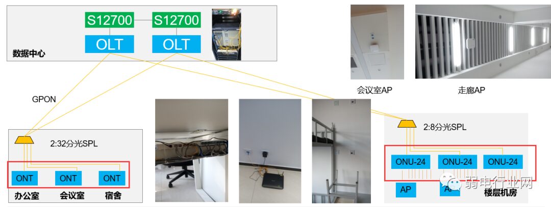
5. Examples of All-Optical Network Architecture
Other examples of all-optical networks: these four major cases are widely applied and worth examining closely.
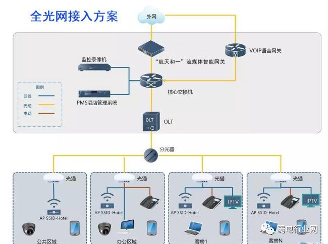
1. Office Building All-Optical Network Access Plan
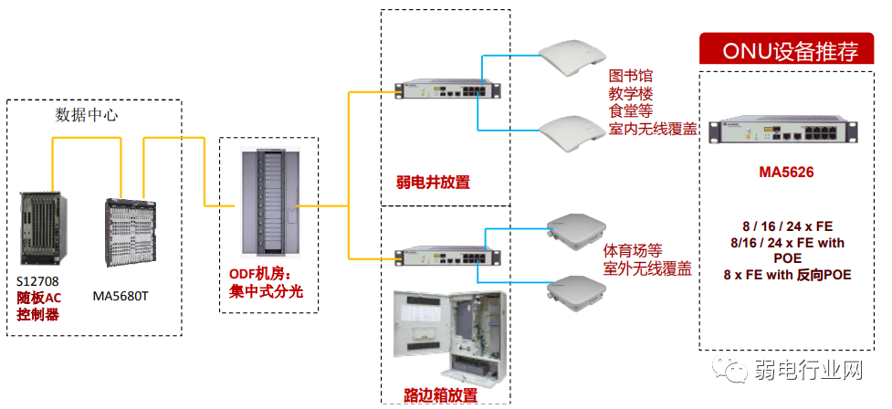
2. All-Optical Network Wireless Coverage Plan
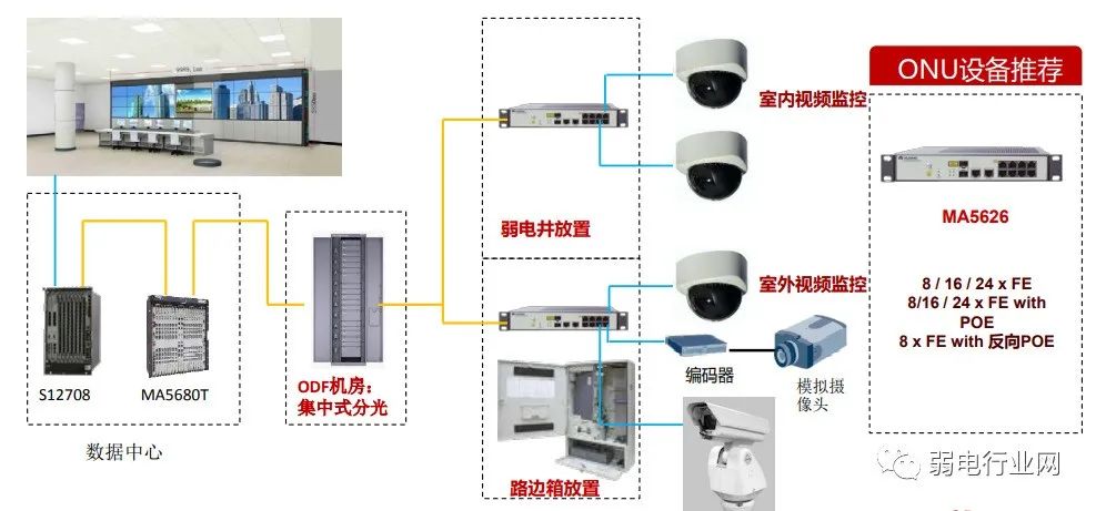
3. All-Optical Network Supporting Video Surveillance
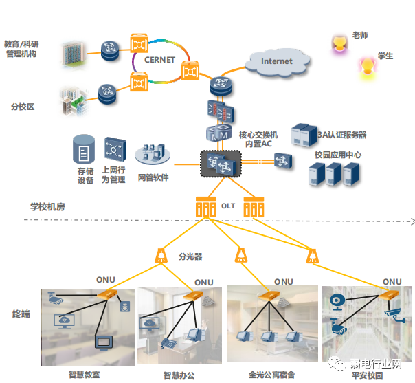
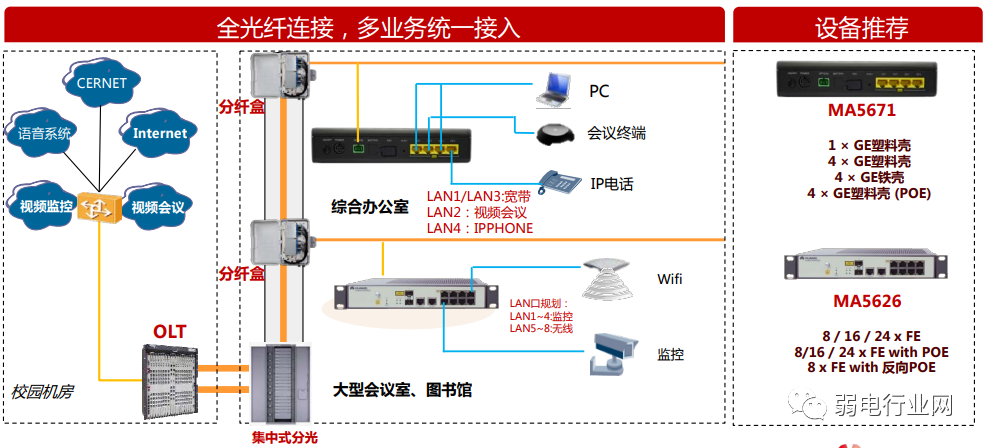
4. All-Optical Campus Networking Framework