When it comes to dToF sensors, the well-known applications mainly involve measuring distance, measuring angles, and gesture recognition. Of course, I won’t introduce these conventional uses today; instead, I will present a “new” method for using dToF sensors: measuring the types of liquids!
This is also the first prize project of the Ams Osram Optoelectronic Design Competition, created by the user of Electronic Forest, “Cherry Big Ball”: Measurement of liquid refractive index and type identification based on dToF technology.
Due to the length of the article, many interesting popular science contents from the project report have been omitted. Interested readers can click the link below to read the full article to view the complete project report.
“Using dToF sensors to measure liquid types” sounds incredible, but if we delve into its principles, it is essentially a variant of distance measurement. As we know, as a direct time-of-flight (dToF) sensor, dToF calculates distance by measuring the time it takes for a light pulse to travel from the emitter to the reflector. Therefore, if light passes through media with different refractive indices, the speed of propagation will change, leading to variations in flight time, which in turn affects the distance measurement results. This is the key point used to measure the refractive index.
Principle
Refraction is the phenomenon where light changes direction when it enters a different medium. The direction and angle of deflection can be calculated using Snell’s law, which is summarized in high school physics:
n1sinθ1 = n2sinθ2
Where: n1 and n2 are the refractive indices of the incident and refracting media, respectively, and θ1 and θ2 are the angles of incidence and refraction, respectively. In university physics, when discussing optics and refraction phenomena, an experiment is often conducted:
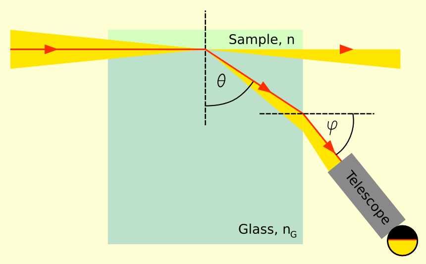
By adding the liquid to be tested on one side of the glass and using an angle-measuring observation lens, when half of the view appears black and half appears bright, record the current angle to measure the refractive index of the solution.
A small experiment can be conducted to observe this by shining a laser pointer at the side of a tank filled with water.
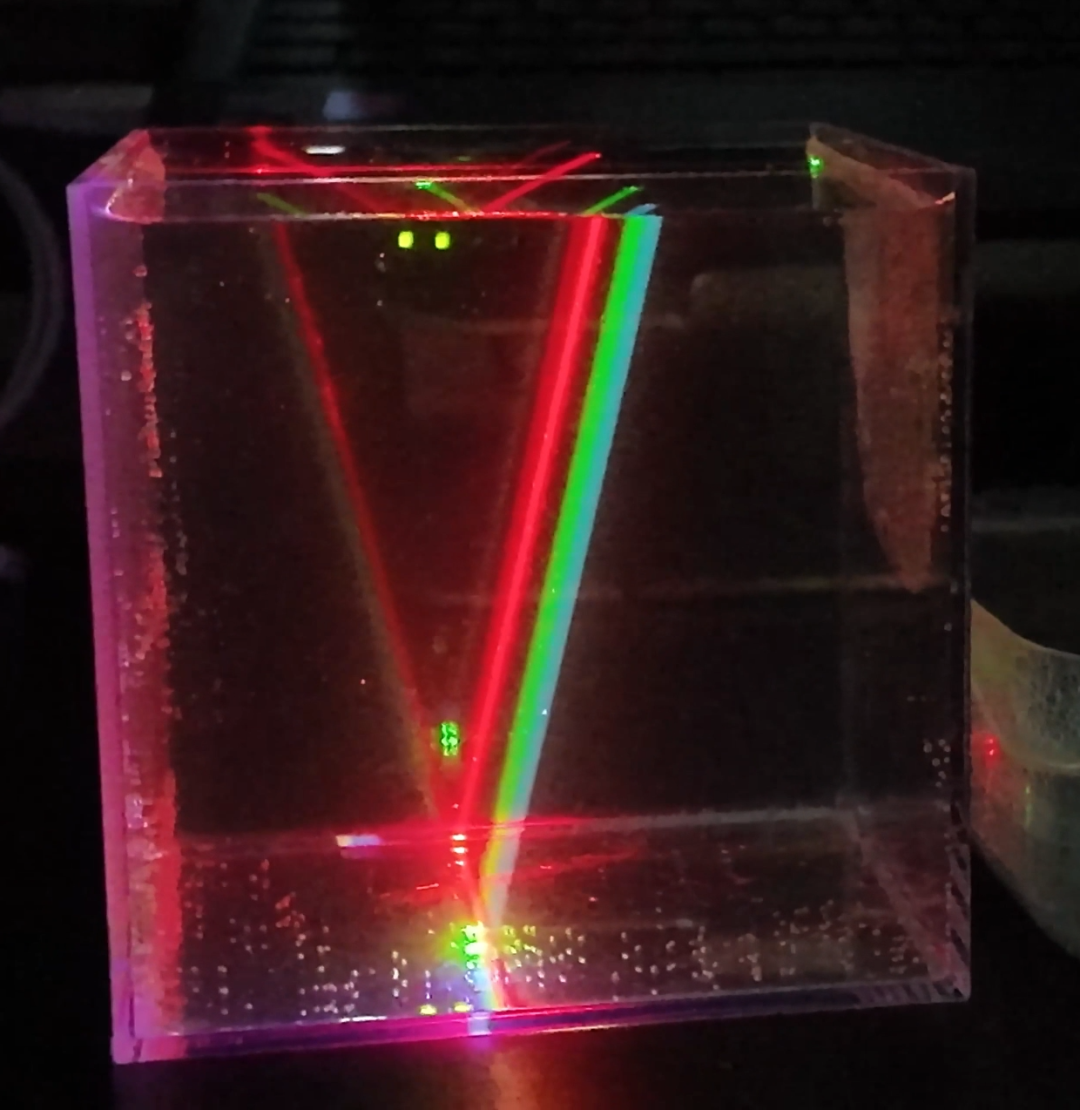
When the laser pointer shines into the water, it can be seen that the light indeed bends, and the angles of deflection for the three colors are different (dispersion occurs). The direction and angle of deflection can also be calculated using more complex formulas (the formulas are too advanced to discuss here), typically described by the empirical Sellmeier equation:
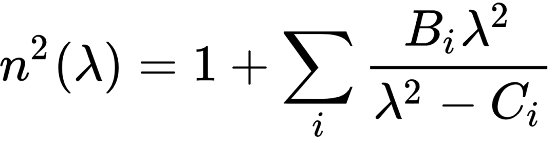
【Note: This empirical equation does not perfectly fit the results, and there are still errors. Additionally, there are other fitting equations】
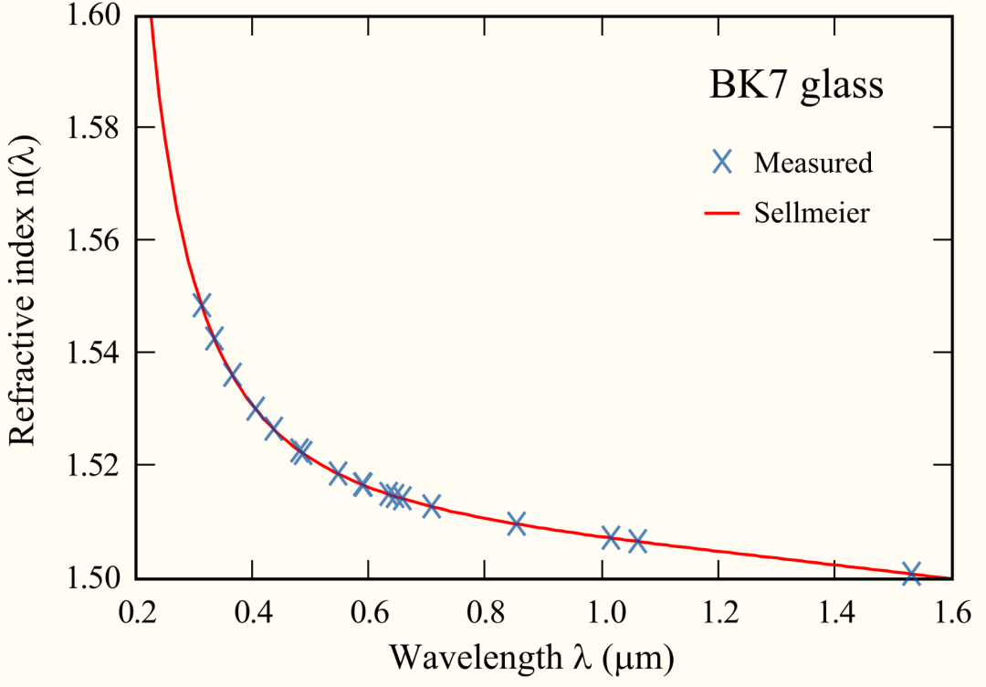
The above image compares the Sellmeier equation with actual measurement results, reflecting the relationship between refractive index and wavelength.
However, this does not explain the essence of refraction. In fact, refraction is closely related to the change in the speed of light; the phenomenon of refraction is actually caused by the change in the speed of light. Why does the speed of light change when it penetrates a medium? The specific physical knowledge involved is too extensive to elaborate here (refer to textbooks on electromagnetic fields and waves or optics), but the core conclusion is:
-
Light is an electromagnetic wave, and its speed in a vacuum is 299792458 m/s (this number is the exact value defined by physics, not an estimate).
-
Electromagnetic waves always travel slightly slower in any medium, and this value is affected by the material of the object.
-
Different frequencies of electromagnetic waves are affected differently by the medium; higher frequency electromagnetic waves slow down more significantly (this is also the main reason for the formation of rainbows).
Because light slows down when it enters a medium, it appears that the direction of the light changes when it enters the water surface. Therefore, the refractive index also satisfies the following relationship: the refractive index (n) is the ratio of the speed of light in a vacuum to the speed of light in a certain medium. This relationship can be expressed by the following formula:
n = c / v
Where:
-
n is the refractive index
-
c is the speed of light in a vacuum
-
v is the speed of light in that medium
From this formula, it can be seen that the larger the refractive index, the slower the speed of light in that medium. In other words, the speed of light in a medium is inversely proportional to the refractive index. For example, the refractive index in air is about 1.00029, almost the same as in a vacuum, so we can approximate that the speed of light is hardly affected; while in water, the refractive index is about 1.33, and the speed of light slows down to about 3/4 of the speed of light in a vacuum. Understanding the origin of the refractive index allows us to combine it with sensor design experiments.
Experiment
Before the experiment, we first clarify the principles of the sensor and need to understand some terms in the sensor manual:
-
FoI (Field of Illumination): The range of active illumination by the VCSEL laser emitter of the sensor.
-
FoV (Field of View): The range that the sensor’s receiving end can detect through the incident lens.
-
SPAD (Single Photon Avalanche Diode): The sensitive element at the receiving end of the sensor.
-
TDC (Time to Digital Converter): Responsible for recording the time from when the laser is emitted until the SPAD receives the signal and converting it into a digital record in the chip.
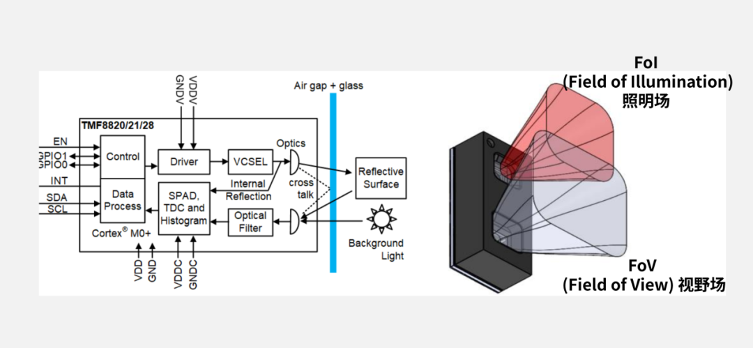
The measurement principle uses a series of pulses generated by the VCSEL. These pulses illuminate the FoI using an MLA (Micro Lens Array). The object reflects these light rays back to the receiver optical lens of the TMF8821, reaching the SPAD array. The TDC then measures the time it takes for these pulses to travel from emission to return to the receiver and accumulates this time information into intervals within a histogram. Since we assume that the speed of light in common environments does not change, the time of flight of the laser and distance becomes a fixed relationship. This is why the sensor is referred to as ToF (Time-of-Flight).
When the TMF8821 emits pulses at a frequency of 550 kHz, the histogram generated by the DC clearly shows reflection peaks from objects at different distances, as shown below:
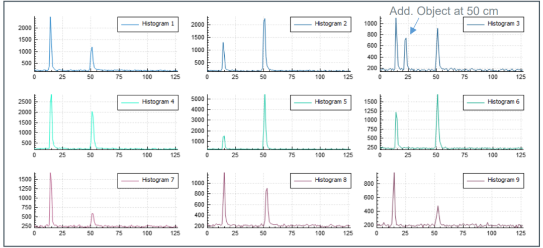
The chip interprets the histogram information. Taking the histogram of regions 2 and 3 in the above image as an example, there was originally an object at the 50 cm position in the histogram, and after adding a new object at 50 cm, a peak will appear at the 25 data position in the histogram, indicating that there is an object reflecting the emitted light at the 25 data position (corresponding to 50 cm).
Next comes the real problem-solving approach:
The information output by the TMF8821 sensor is the distance in each direction, and this distance is based on placing the sensor in air for measurement, and using half the time of the light rays hitting the obstacles and returning to calculate the distance by multiplying by the speed of light in air. Conversely, dividing the distance by the speed of light gives the time of flight of the photons.
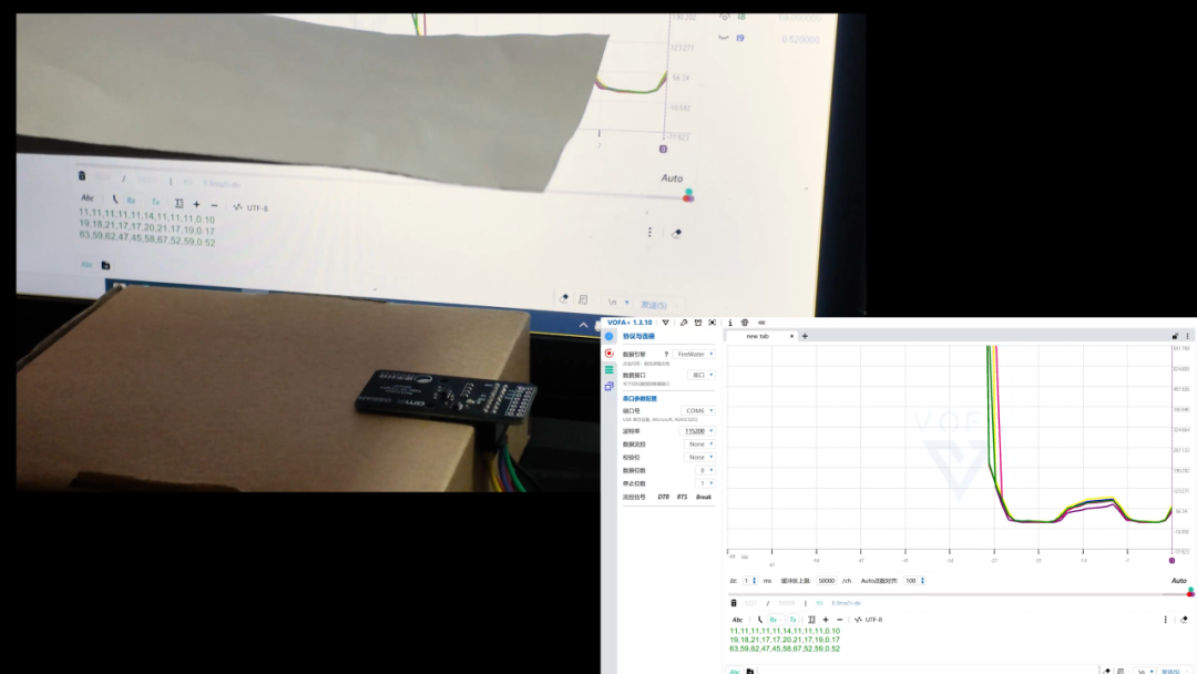
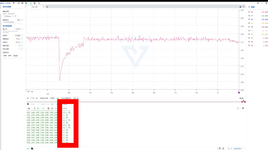
After successfully driving the sensor, the distance and values corresponding to the objects in front can be seen through the serial port.
However, the problem I tackled precisely utilized the “common environment where the speed of light does not change” special case. As mentioned in the theoretical section, in some media, light does not travel at the speed of 3.0×10⁸ m/s in air. The sensor does not actually know that the medium in front is not air; the light is calculated as if it were traveling at standard speed even after being slowed down by the medium, so the distance measured through a certain thickness of water will be greater than the distance in the same thickness of air.
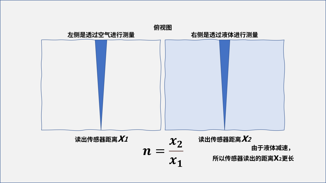
In reality, the distance has not changed; it is the change in the speed of light that causes the change in flight time. Simple mathematical calculations can show:
x1 = c∗t1= v∗t2
x1 = c∗t2
v = c∗x1/x2
The real speed of light in the medium is the speed of light multiplied by the ratio of the real distance X1 to the distance measured through the medium X2. With the real speed, the refractive index of the medium can be calculated.
n = x2/x1
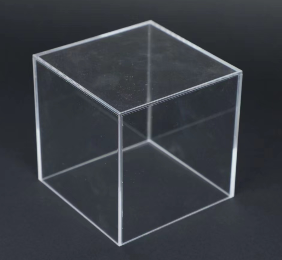
Thus, after a long detour, we arrive at the formula for calculating the refractive index of the medium. Next, we just need to find a suitable container that is thick enough and has a thin outer wall to reduce interference from the container wall. I chose a water tank made of thin acrylic.
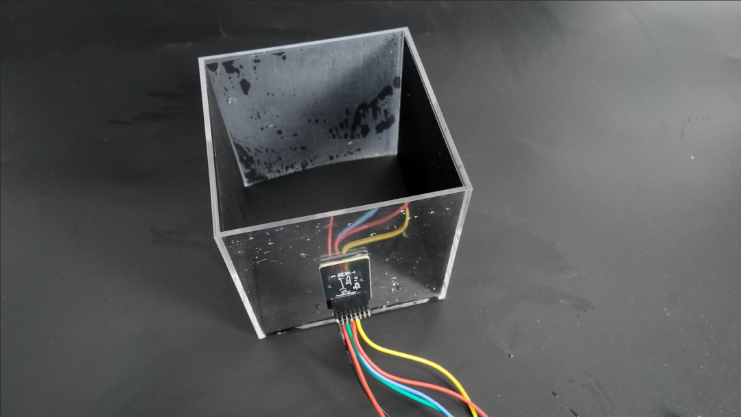
To increase the signal-to-noise ratio of the reflection, I attached a layer of black matte plastic to one side of the inner wall of the tank (white or mirror-like reflections would increase errors).
-
First, measure the front and back thickness of the empty tank, denoted as X1.
-
Next, fill the tank with water and measure again, recording the distance as X2.
-
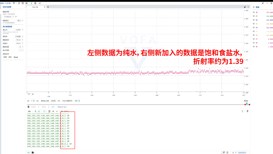
Using the formula, it can be calculated that the refractive index of water is approximately 1.35, which is close to the theoretical value of 1.33.
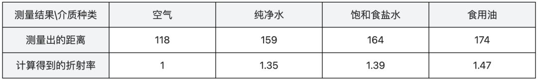
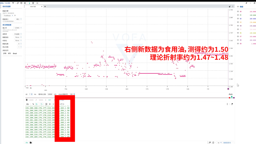
By replacing the liquid with saturated saltwater (approximately 1.39) and cooking oil (approximately 1.47), the experiment was repeated, and the data were all close to the theoretical values. 【For those interested in the experimental content, you can click the link below to read the full article to view the complete experimental video】
Project
Design Ideas
Hardware Aspects
-
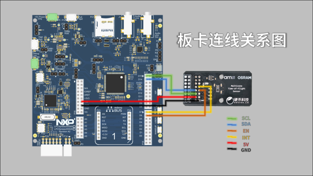
LPC55S69 Main Control: Responsible for driving the dToF module, high-precision timing, and data processing 【The LPC55S69-EVK is an evaluation and development platform launched by NXP Semiconductors based on the LPC5500 series dual-core Arm Cortex-M33 microcontroller, with a maximum operating frequency of 150 MHz. The expansion interfaces on the board are also compatible with Arduino, making it easy to expand more functions later. The Arduino expansion interface used in this project is connected as shown in the image】;
-
dToF Module: Emits/receives light pulses and measures the time of flight in air and liquids;
-
Optical Structure: Designed to fix the liquid in a transparent container, ensuring that the light pulses penetrate the medium vertically (customized a square acrylic box with a wall thickness of 3mm online).
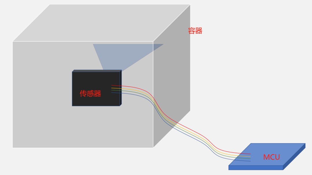
The installation method is shown in the image above. Since the sensor end needs to rest against the container, it inevitably comes into contact with the liquid. To ensure safety, the sensor board and controller board are fixed separately, with wires used for reinforcement connections in between.
Communication Code, Key Sensor Function Code
You can click the link below to read the full article to see it~
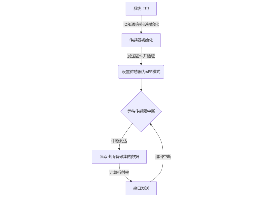
Main Program Flowchart
Function
Display
Implemented as shown in the image above. Since the same container is used for each experiment and the sensor is fixed on the side, the front and back thickness of the container is directly fixed in the code. The following images show pure water, cooking oil, and saturated saltwater (1.35, 1.47, 1.39).
By simply determining the range of refractive indices based on the type of solution in advance, creating a lookup table embedded in the program, the program can automatically measure and classify.
PS: The sensor also has a mode for directly reading from the histogram. If the histogram is used directly, it should be able to solve some artifacts caused by reflections, which can be a direction for future attempts.
Conclusion
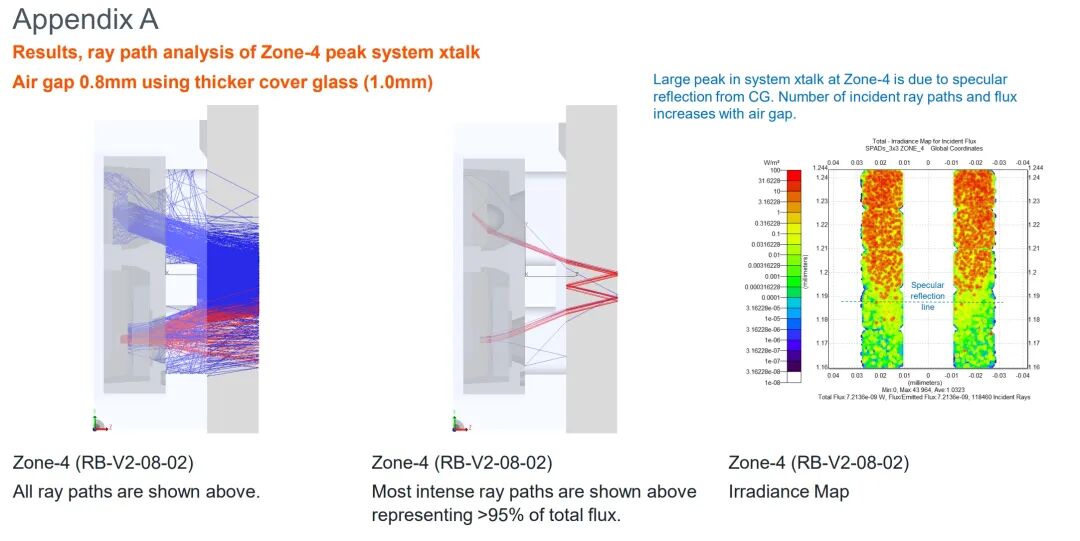
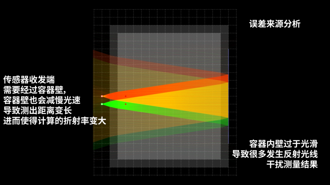
To summarize, the errors in the experimental results mainly come from two aspects: first, the limitations of measurement accuracy, and second, the simplification of calculations without accounting for the refractive effects of the container walls (such as the interference of acrylic material on the light path, which is also mentioned in the official optical design guide regarding the impact of container walls and air gaps on results).
Additionally, the choice of materials and reflection conditions in the experiment also needs optimization—for example, white reflective stickers may cause signal saturation, while using gray materials can balance the signal-to-noise ratio.
When testing different liquids, it was found:
1. The refractive index of saturated saltwater is close to that of water.
Although the solubility of sodium chloride is not high (about 36g/100g of water at room temperature), the actual preparation may result in limited ion density due to insufficient dissolution or concentration, leading to insignificant changes in refractive index.
2. The measurement of cooking oil has a large deviation.
The main reason is speculated to be the presence of suspended impurities in the purchased rice oil. When pouring the oil, bubbles are generated in the container, which can scatter light and interfere with the SPAD receiving signal; impurities can cause local inhomogeneity in the refractive index of the medium, affecting the stability of the light path.
3. Limitations in solvent selection.
Theoretically, using highly soluble solutes (such as sucrose) can significantly change the refractive index of the liquid, but further verification was not conducted due to time constraints. (If there were a 10cm thick diamond to measure the refractive index, the phenomenon would certainly be more pronounced).
4. Errors caused by misalignment of the sensor.
In preliminary tests, it was found that if the sensor is not parallel to the side, there will be some errors, resulting in distance changes.
Improvement Directions:
-
Pre-treating samples: Remove bubbles and suspended matter from the oil through centrifugation or filtration, or choose high-purity reagent-grade cooking oil;
-
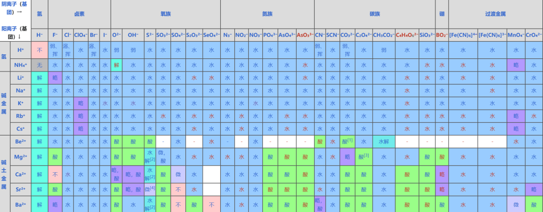
Optimizing solutes: Select solutes with large refractive index gradients (such as glycerol) or materials with high refractive indices and high solubility in water, preparing solutions of different concentrations for comparison; the following image shows a common solubility table for salts, which can be used to select easily soluble substances.
-
Container calibration: Measure the thickness of the empty tank separately and subtract its refractive effect from the total optical path. Alternatively, use a larger container to reduce the impact of the container wall (e.g., using a deep bucket for measurement from above the water surface). PS: I saw a rectangular beverage bottle at a convenience store; perhaps such a bottle could reduce the error caused by the container wall.
-
Algorithm upgrade: It is hypothesized that if the board is not pressed parallel, it will form an angle with the opposite container wall, so the principle from the first question could be used to eliminate the errors caused by the angle, allowing for more accurate results even with an angle.
Expanding on this, if the solute and standard refractive index are known, this project could be extended to measure different refractive indices and back-calculate the concentration of the solute, which should have good applications in industrial production.

Click to read the original text to view the complete project report
END
This dToF optoelectronic design competition awarded the following excellent projects with first, second, and third prizes:
✦ First Prize ✦
“Cherry Big Ball”
Measurement of liquid refractive index and type identification based on dToF technology
https://www.eetree.cn/project/detail/3854
✦ Second Prize ✦
“ixbwer”
Non-contact gesture control game based on TMF8821
https://www.eetree.cn/project/detail/3860
• • •
“Little Yangyang”
Gesture multimedia keyboard based on TMF8821
https://www.eetree.cn/project/detail/3844
• • •
“Paper Blue from the Southeast”
dToF sensor module based on TMF8821 paired with RP2040 game console to complete planar angle measurement function
https://www.eetree.cn/project/detail/3829
✦ Third Prize ✦
“Pulsar2”
Gesture recognition menu based on TMF8821
https://www.eetree.cn/project/detail/3839
• • •
“HonestQiao”
Angle measurement and gesture recognition based on Raspberry Pi 5 + TMF8821
https://www.eetree.cn/project/detail/3831
• • •
“Evergreen”
Non-contact gesture control game based on TMF8821
https://www.eetree.cn/project/detail/3836
• • •
“obrulviser”
Liquid discrimination device based on TMF8821
https://www.eetree.cn/project/detail/3855
• • •
“Maple Snow Day”
PC universal controller based on dToF gesture recognition
https://www.eetree.cn/project/detail/3843