
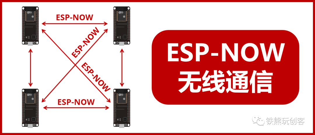
This article is co-authored by Tie Xiong and Mo.
During the journey of learning Arduino development, wireless communication is a necessary hurdle. Wireless communication frees us from the constraints of wires, offering more flexibility, with communication distances ranging from several meters to even kilometers, depending on the wireless module used. Common wireless communication methods include Bluetooth, WiFi, LoRa, NB-IoT, etc. This tutorial will focus on another wireless communication protocol developed by Espressif: ESP-NOW. Through this tutorial, you will learn how to apply ESP-NOW technology to our DIY projects.
Hardware Preparation
Development Environment
We will use Arduino software to write the program for this project. As for how to configure the ESP32 development environment in Arduino, it is beyond the scope of this article; please refer to relevant materials.
What is ESP-NOW?
ESP-NOW is another wireless communication protocol developed by Espressif that allows multiple devices to communicate without or not using Wi-Fi. This protocol is similar to the low-power 2.4GHz wireless connection commonly found in wireless mice—devices must pair before communicating. After pairing, the connection between devices is persistent, point-to-point, and does not require a handshake protocol. It is a fast, connectionless communication technology for short data transmission, allowing low-power controllers to directly control all smart devices without connecting to a router, suitable for scenarios such as smart lights, remote controls, sensor data backhaul, etc.
After using ESP-NOW communication, if a device suddenly loses power, it will automatically reconnect to the corresponding node and resume communication once it restarts.
ESP-NOW supports the following features:
-
Unicast packet encryption or unencrypted communication; -
Mixing encrypted paired devices and unencrypted paired devices; -
Can carry a maximum payload of 250 bytes; -
Supports setting a send callback function to notify the application layer of frame send failure or success.
Similarly, ESP-NOW also has some limitations:
-
Broadcast packets are not currently supported; -
Limitations on encrypted paired devices: a maximum of 10 encrypted paired devices in Station mode; a maximum of 6 encrypted paired devices in SoftAP or SoftAP + Station mixed mode. Unencrypted paired devices can be several, with the total number of encrypted and unencrypted devices not exceeding 20; -
Payload limit of 250 bytes.
ESP-NOW Communication Methods
ESP-NOW supports multiple communication methods:
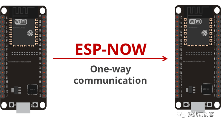
One-to-One Unidirectional Communication
One-to-one unidirectional communication is the simplest communication method, where one device is responsible for sending data, and another device is responsible for receiving data, as shown in the figure below:
One-to-Many Unidirectional Communication
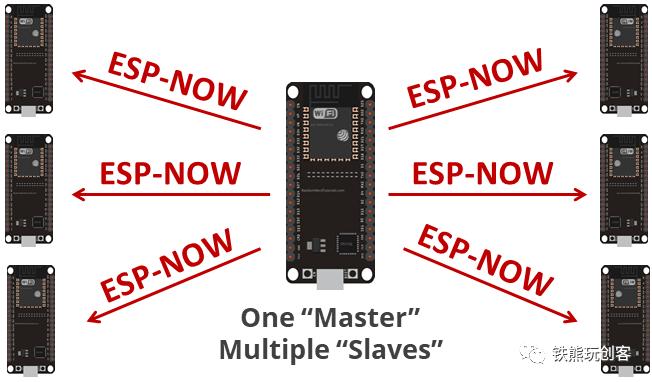
One-to-many unidirectional communication means one device is responsible for sending data, while multiple devices are responsible for receiving data. The data sender is similar to a remote control, and the data receivers can control different devices, as shown in the figure below:
Many-to-One Unidirectional Communication
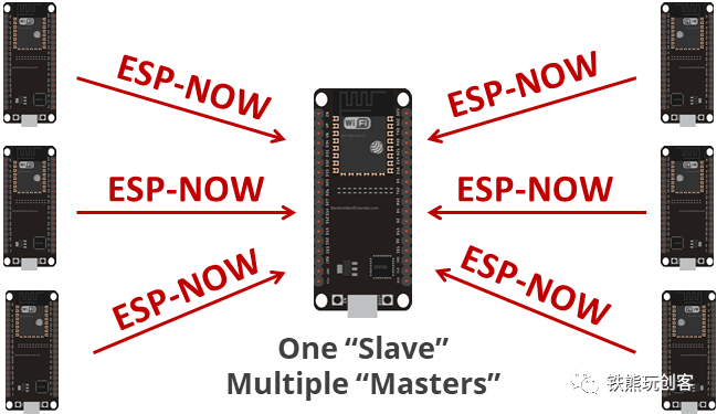
Many-to-one unidirectional communication means one device is specifically responsible for receiving data, while the other devices send data to it. This scenario is mainly used for multiple devices collecting different sensor data and then summarizing the data to a center or main controller, as shown in the figure below:
Bidirectional Communication
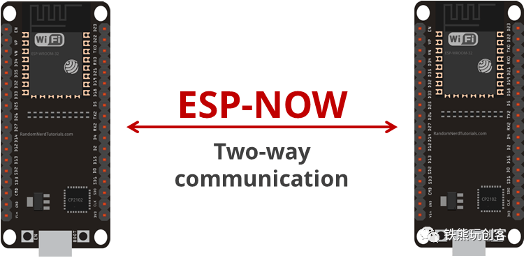
Compared to unidirectional communication, bidirectional communication means both parties can send and receive data. One-to-one bidirectional communication is shown in the figure below:
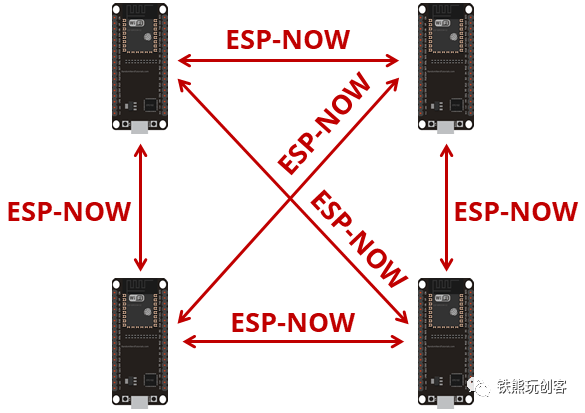
In bidirectional communication, more devices can also be added to exchange data pairwise, as shown in the figure below:
Of course, all of these communications are not limited to communication between ESP32 development boards; all devices that support ESP-NOW can communicate with each other, such as between ESP32 and ESP32, ESP8266 and ESP8266, or even between ESP32 and ESP8266.
Next, we will introduce how to use ESP-NOW for communication through actual programs, taking ESP32 as an example; the methods for other development boards are similar.
Getting the MAC Address
ESP-NOW is a point-to-point communication method, and when sending data, you need to specify the receiving device, just like you must know the QQ number of the other party when sending a QQ message. Here, we generally use the device’s MAC address as a credential to distinguish different receiving devices. So what is a MAC address? A MAC address, also called a physical address or hardware address, is unique for each device and is different at the time of factory production.
Next, we will use Arduino code to obtain the MAC address of the ESP32 development board:
#include <WiFi.h>

void setup() {
  Serial.begin(9600);
  Serial.println();
#ifdef ESP8266
  Serial.print("ESP8266 Board MAC Address:  ");
  Serial.println(WiFi.macAddress());
#elif defined ESP32
  WiFi.mode(WIFI_MODE_STA);
  Serial.print("ESP32 Board MAC Address:  ");
  Serial.println(WiFi.macAddress());
#endif
}

void loop() {

}
Upload the program and open the serial monitor to obtain the MAC address of different development boards:
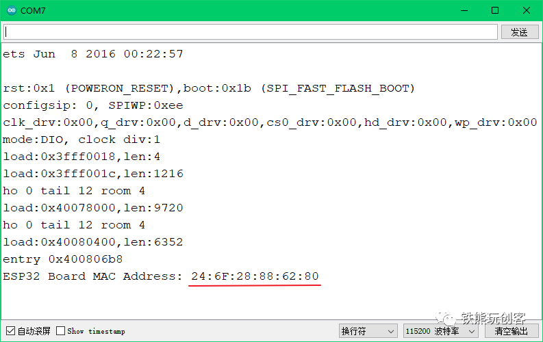
Where 24:6F:28:88:62:80 is the MAC address of the ESP32 development board, which consists of 6 hexadecimal digits. Each development board has a corresponding unique MAC address. We record this MAC address, as we will use it later.
Of course, in ESP-NOW communication, there is not just one development board; we will record the MAC addresses of other development boards in the same way.
ESP-NOW Data Sending
After obtaining the MAC address, let’s first see how to write the program to send data.
Here, we take the controlling board as an example, sending data from the light sensor and sound sensor on the controlling board to another controlling board. Let’s first look at the complete program and then explain:
#include <WiFi.h>
#include <esp_now.h>

// Set the pin numbers for the sound sensor and light sensor on the controlling board
const int soundPin = 36;
const int lightPin = 39;

// Set the data structure
typedef struct struct_message {
  String board_name;
  double light;
  double sound;
} struct_message;

struct_message myData;

// MAC address of the receiving device
uint8_t broadcastAddress[] = {0x24, 0x6F, 0x28, 0x88, 0x62, 0x80};

// Data sending callback function
void OnDataSent(const uint8_t *mac_addr, esp_now_send_status_t status) {
  char macStr[18];
  Serial.print("Packet to: ");
  snprintf(macStr, sizeof(macStr), "%02x:%02x:%02x:%02x:%02x:%02x",
           mac_addr[0], mac_addr[1], mac_addr[2], mac_addr[3], mac_addr[4], mac_addr[5]);
  Serial.println(macStr);
  Serial.print("Send status: ");
  Serial.println(status == ESP_NOW_SEND_SUCCESS ? "Delivery Success" : "Delivery Fail");
  Serial.println();
}

void setup() {
  Serial.begin(9600);

  // Initialize ESP-NOW
  WiFi.mode(WIFI_STA);
  if (esp_now_init() != ESP_OK) {
    Serial.println("Error initializing ESP-NOW");
    return;
  }

  // Set the data sending callback function
  esp_now_register_send_cb(OnDataSent);

  // Bind the data receiving end
  esp_now_peer_info_t peerInfo;
  memcpy(peerInfo.peer_addr, broadcastAddress, 6);
  peerInfo.channel = 0;
  peerInfo.encrypt = false;

  // Check if the device is paired successfully
  if (esp_now_add_peer(&peerInfo) != ESP_OK) {
    Serial.println("Failed to add peer");
    return;
  }
}

void loop() {
  // Set the data to be sent
  myData.board_name = "mPython_#1";
  myData.light = analogRead(lightPin);
  myData.sound = analogRead(soundPin);

  // Send data
  esp_err_t result = esp_now_send(broadcastAddress, (uint8_t *) &myData, sizeof(myData));

  // Check if the data is sent successfully
  if (result == ESP_OK) {
    Serial.println("Sent with success");
  }
  else {
    Serial.println("Error sending the data");
  }
  delay(1000);
}
This example demonstrates sending data detected by one ESP32 development board (here taken as the controlling board) to another ESP32 development board.
First, we include the relevant headers for ESP-NOW: WiFi.h and esp_now.h. Then we define the sensor pins and a structure named myData, which consists of three different data: the board name (board_name), light value (light), and sound value (sound). The board name is of string type, while the light and sound values are floating-point data. If we have multiple sensor data detection ends, we can distinguish the data from devices by the board name.
Next, we define the MAC address of the receiving device with uint8_t broadcastAddress[] = {0x24, 0x6F, 0x28, 0x88, 0x62, 0x80}.
In addition, we registered a data sending callback function OnDataSent(), which provides feedback on the sending status of ESP-NOW data. This example sends the light and sound values to the specified MAC address every second.
In setup(), we first initialize the ESP-NOW functionality, then set the data sending callback function and bind the MAC address of the data receiving end.
In loop(), we continuously read the light and sound values, assign them to the myData structure, and send them to the receiving end while checking if the data is sent successfully.
ESP-NOW Data Receiving
Next, let’s see how to write the program for the receiving end.
Write the following program and upload it to another controlling board (the one whose MAC address was printed earlier).
#include <WiFi.h>
#include <esp_now.h>

// Set the data structure
typedef struct struct_message {
  String board_name;
  double light;
  double sound;
} struct_message;

struct_message myData;

// Data receiving callback function
void OnDataRecv(const uint8_t * mac, const uint8_t *incomingData, int len) {
  memcpy(&myData, incomingData, sizeof(myData));
  Serial.print("board_name: ");
  Serial.println(myData.board_name);
  Serial.print("light: ");
  Serial.println(myData.light);
  Serial.print("sound:");
  Serial.println(myData.sound);
  Serial.println();
}

void setup() {
  Serial.begin(9600);

  // Initialize ESP-NOW
  WiFi.mode(WIFI_STA);
  if (esp_now_init() != 0) {
    Serial.println("Error initializing ESP-NOW");
    return;
  }

  // Set the data receiving callback function
  esp_now_register_recv_cb(OnDataRecv);
}

void loop() {

}
Again, we include the relevant headers for ESP-NOW: WiFi.h and esp_now.h. Then we define the sensor pins and a structure named myData, which consists of three different data: the board name (board_name), light value (light), and sound value (sound), identical to what was defined in the data sending end.
We register a data receiving callback function OnDataRecv(), which provides feedback on the receiving status of ESP-NOW data. When a message from other development boards is received, it saves the message to the myData structure and prints the received message to the serial monitor.
Here, the message reception of ESP-NOW is non-blocking, meaning it is not affected by the delay function delay(). This allows the loop() to execute other tasks without affecting communication between boards. The same board can act as both a receiver and sender without interference. It can receive messages from multiple boards, provided they maintain the same structure. You can also use ordinary single-type data types, such as strings, instead of structures. We use structures here because the data types to be sent are multiple, making structures relatively flexible.
Experimental Results
Upload the sending and receiving programs to the two ESP32 development boards, then open the serial monitor to see the effect.
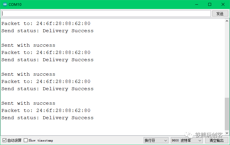
The serial monitor for the sending end is as follows:
The serial monitor for the receiving end is as follows:
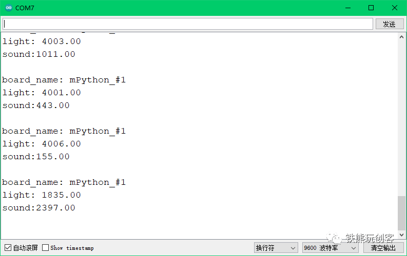
As you can see, both the sending and receiving devices are functioning normally, and the corresponding information is outputted in the serial monitor.
Conclusion
Thus, the simple application of ESP-NOW has been completed, and we have learned a new wireless communication method. The above only demonstrates a simple example of one-to-one data sending and receiving; in fact, one-to-many, many-to-one, and many-to-many data sending and receiving follow the same principle, requiring only the addition of corresponding code.
You can try reducing the data sending interval in the tutorial to see how fast ESP-NOW can be. In future projects, if you need to extensively use ESP series development boards, the ESP-NOW technology can organically connect all DIY projects together, achieving true interconnectivity, which we will gradually explain in future lessons.
See you next time!
References: https://randomnerdtutorials.com/esp-now-esp32-arduino-ide/

Give a thumbs up for support!
