Click on the blue text above to follow us.
1
Project Overview
The smart car is a robot that uses wheels as a mobile mechanism and can achieve autonomous driving; it is also known as a wheeled robot. Due to its intelligent characteristics, it can be applied in environments unsuitable for humans, such as disaster rescue and outdoor exploration. Smart cars differ from remote-controlled cars, as the latter require an operator to control their steering, start and stop, and forward and backward movement, with speed control. Common model cars belong to this category of remote-controlled vehicles. Smart cars can control their driving direction, start and stop, and speed through computer programming without human intervention, and their driving modes can be changed by modifying their programs.
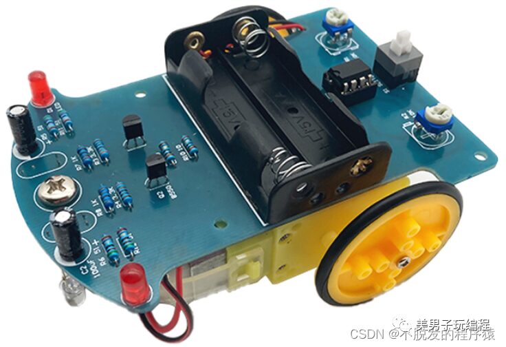
The typical features of smart cars include:
1. At least one microcontroller to control driving direction, start and stop, and speed.
2. Multiple sensors with various functions to gather information about the external environment, enabling the controller to make accurate decisions.
2
Project Architecture
This section will introduce a wireless remote-controlled smart car based on Arduino and LabVIEW, which can achieve both autonomous (line-following and obstacle-avoidance) and remote control functions, with the ability to switch between the two modes. The smart car uses Arduino as the control core, while the host software is LabVIEW, and the two communicate wirelessly through the APC220 wireless data transmission module. The overall block diagram of the wireless remote-controlled smart car is shown below:
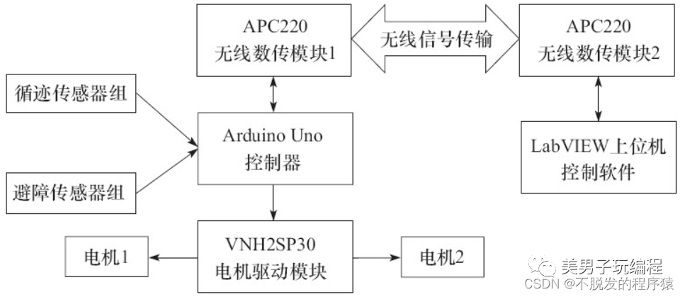
The car body of the smart car adopts a three-wheel model with two drive wheels and one omnidirectional wheel. The driving motor is a DC reduction motor, and the motor driver module uses the VNH2SP30 module. The line-following sensor is the OPENJUMPER infrared line-following sensor OJ-CG307, and the obstacle-avoidance sensor is the OPENJUMPER infrared obstacle-avoidance sensor OJ-CG303.
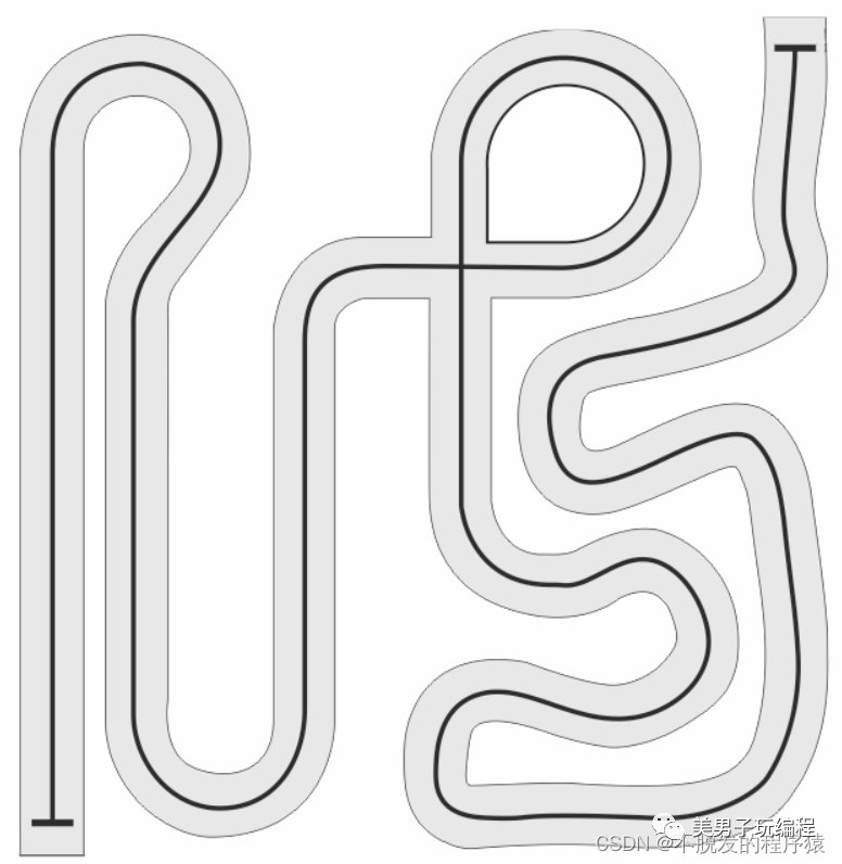
The line-following area for the smart car is a white background with a black line, approximately 10mm wide, and the area size is about 200cm×300cm.
3
Sensors and Controllers
3.1 Sensors
The wireless remote-controlled smart car introduced in this section can achieve both autonomous and remote control functions, with the ability to switch between the two modes. When the car is in remote control mode, the operator uses the LabVIEW host software to send remote control commands to the Arduino controller on the car via the APC220 serial wireless module, prompting the car to perform specified actions. When the car is in autonomous mode, the Arduino controller on the car uses four infrared line-following sensors and one infrared obstacle-avoidance sensor to obtain signals regarding the car’s position relative to the black line and whether there are obstacles ahead, controlling the DC reduction motor based on the logic set in the program to achieve line-following and obstacle-avoidance functions.
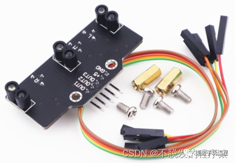
The infrared line-following sensor module uses the infrared reflection from the module itself (dark colors reflect weakly, light colors reflect strongly) to provide tracking for the line-following robot, allowing it to detect black lines on a white background or white lines on a black background; it outputs a high level when detecting a white line and a low level for a black line.
The infrared obstacle-avoidance sensor emits infrared light and determines whether there are obstacles ahead based on the reflected infrared light. It outputs a high level when there are no obstacles and a low level when there are obstacles, with an indicator light showing the status: green for no obstacles and red for obstacles. It also has a built-in 38kHz signal generator, providing strong anti-interference capability. The detection distance can be adjusted using the 2KΩ potentiometer on the module.
The infrared line-following sensor module is shown in the figure below:
The infrared obstacle-avoidance sensor module is shown in the figure below:

3.2 Controller
Generally, DC motors require a large driving current, and controllers like Arduino output logical levels that cannot directly drive DC motors, especially high-power reduction motors. Therefore, driver components are needed to provide the working current for the DC motors.
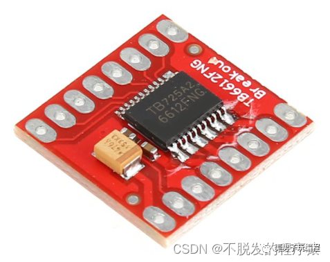
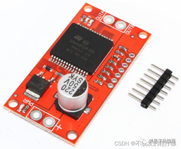
The commonly used DC motor driver modules among Arduino enthusiasts include the L298 module and the VNH2SP30 module.
The L298 motor driver module is relatively inexpensive, and a single L298 chip can drive two DC motors simultaneously. It is commonly used by Arduino enthusiasts for making robot cars; however, it has low conversion efficiency and generates a lot of heat, making it unsuitable for driving high-current DC motors, as it can easily cause issues such as chip “hanging” when driving high-current motors.
The VNH2SP30 module has advantages such as high driving current and high conversion efficiency, but a single VNH2SP30 chip can only drive one DC motor. If two DC motors are to be driven, two VNH2SP30 chips are required.
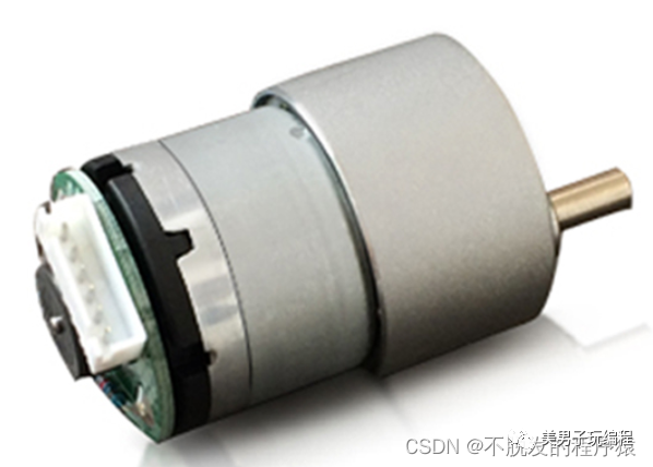
To ensure that the remote-controlled smart car has a good power system and a certain load capacity, DC reduction motors are selected as the power source for the entire remote-controlled smart car, along with granular tires to enhance grip.
4
Hardware Environment
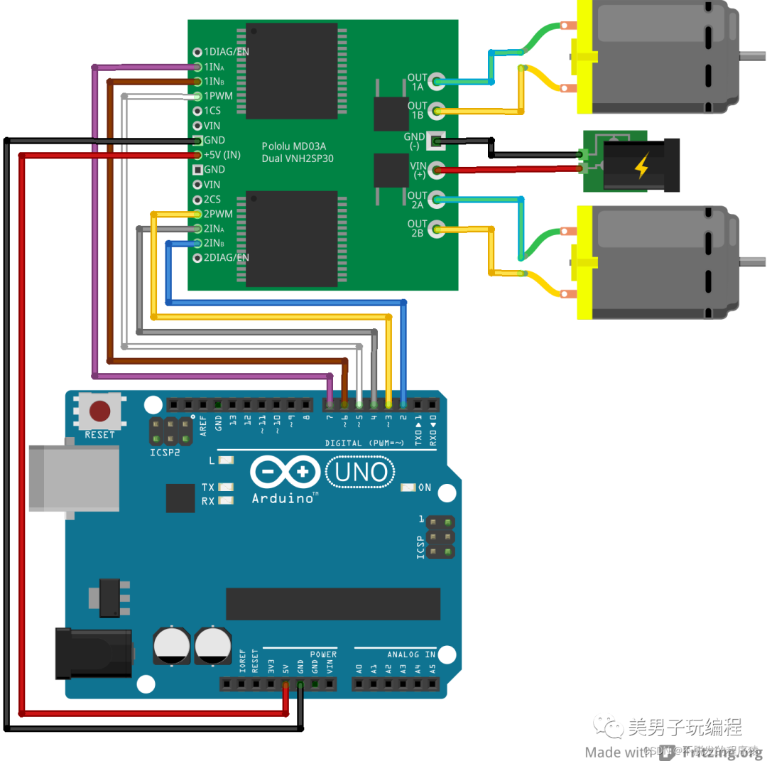
Connect the two ends of the two DC reduction motors to OUT1A, OUT1B, OUT2A, and OUT2B on the VNH2SP30 motor driver module, with no polarity or motor direction distinction. If the motors are rotating in opposite directions, the connection wires can be swapped during debugging. Connect the +5V (IN) and GND of the VNH2SP30 motor driver module to the +5V and GND on the Arduino Uno control board to provide working voltage for the motor driver module.
Connect the 1INA, 1INB, and 1PWM of the VNH2SP30 motor driver module to digital ports D7, D6, and D5 on the Arduino Uno control board to provide steering and speed control signals for motor 1; connect the 2INA, 2INB, and 2PWM of the VNH2SP30 motor driver module to digital ports D4, D2, and D3 on the Arduino Uno control board to provide steering and speed control signals for motor 2. It is important to note that 1PWM and 2PWM must be connected to digital ports with analog output (PWM) functionality.
The hardware connections between the Arduino controller and the driver and motor parts are shown in the figure below:
Connect one APC220 module to the Arduino Uno control board as follows:
APC220 TXD → Arduino Uno control board RXD, APC220 RXD → Arduino Uno control board TXD, APC220 VCC → Arduino Uno control board 5V, APC220 GND → Arduino Uno control board GND.
Connect another APC220 module through the FT232RL adapter board as follows:
APC220 TXD → FT232RL adapter board RXD, APC220 RXD → FT232RL adapter board TXD, APC220 VCC → FT232RL adapter board 5V, APC220 GND → FT232RL adapter board GND.
Connect the four infrared line-following sensors to the digital ports D8, D9, D10, and D11 on the Arduino Uno control board in sequence, corresponding to left 2, left 1, right 1, and right 2 when installing the infrared line-following sensors on the smart car chassis. Connect the infrared obstacle-avoidance sensor to digital port D12 on the Arduino Uno control board and install it at the front end of the car.
5
Arduino Function Design
The installation diagram of the four infrared line-following sensors on the smart car chassis is shown below:
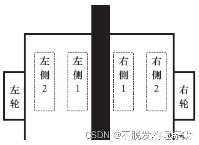
The initial state is that the black line is between the left 1 and right 1 sensors, indicating that the car is in the middle of the black line; when the left 1 sensor detects the black line, it indicates that the car is slightly deviating to the right of the black line and needs to turn left slightly to correct the deviation; when the left 2 sensor detects the black line, it indicates that the car is deviating too much to the right and needs to turn left significantly to correct the deviation; when the right 1 sensor detects the black line, it indicates that the car is slightly deviating to the left of the black line and needs to turn right slightly to correct the deviation; when the right 2 sensor detects the black line, it indicates that the car is deviating too much to the left and needs to turn right significantly to correct the deviation.
The speed control for the remote control part is divided into five levels: low speed, medium-low speed, medium speed, medium-high speed, and high speed, realized through the PWM input signal of the VNH2SP30 motor driver module to switch and adjust speed among the five levels.
The Arduino Uno controller program code is shown below:
#define forward_command   0x00   // Forward command
#define back_command      0x10   // Backward command
#define left_command       0x20   // Left turn command
#define right_command      0x30   // Right turn command
#define stop_command      0x40   // Stop command
#define speed_1           0x50   // Low speed command
#define speed_2           0x60   // Medium-low speed command
#define speed_3           0x70   // Medium speed command
#define speed_4           0x80   // Medium-high speed command
#define speed_5           0x90   // High speed command
byte comdata[3]={0};   // Define array data to store serial command data
int flag = 0;           // Remote/automatic flag, default is remote mode
int INA1 = 7;
int INB1 = 6;
int PWM1 = 5;      // Define motor 1's steering and speed control pins
int INA2 = 4;
int INB2 = 2;
int PWM2 = 3;      // Define motor 2's steering and speed control pins
int Trace_sensor_X1=8;
int Trace_sensor_X2=9;
int Trace_sensor_Y1=10;
int Trace_sensor_Y2=11;      // Define four infrared line-following sensor pins
int Avoidance_sensor=12;     // Define infrared obstacle-avoidance sensor pin
void receive_data(void);      // Receive serial command data
void test_do_data(void);      // Test if the serial command data is correct and execute commands
void forward(void);        // Forward sub-function
void back(void);           // Backward sub-function
void turn_Left(void);        // Left turn sub-function
void turn_Right(void);       // Right turn sub-function
void stop_car(void);             // Stop sub-function
void Automatic_mode(void);      // Automatic mode sub-function
void setup(){  Serial.begin(9600);             // Initialize serial baud rate to 9600  pinMode(INA1, OUTPUT);  pinMode(INB1, OUTPUT);  pinMode(PWM1, OUTPUT);      // Set motor 1's control pins to output state  pinMode(INA2, OUTPUT);  pinMode(INB2, OUTPUT);  pinMode(PWM2, OUTPUT);      // Set motor 2's control pins to output state    pinMode(Trace_sensor_X1, INPUT);  pinMode(Trace_sensor_X2, INPUT);  pinMode(Trace_sensor_Y1, INPUT);  pinMode(Trace_sensor_Y2, INPUT); // Set the infrared line-following sensor's control pins to input state  pinMode(Avoidance_sensor,INPUT); // Set the infrared obstacle-avoidance sensor's control pins to input state    analogWrite(PWM1,150); //left motor  analogWrite(PWM2,150); //right motor    // Set motor speed to medium speed} void loop(){  if (Serial.available() > 0)      // Continuously check if there is data in the serial port   {        receive_data();            // Receive serial command data from the serial buffer        test_do_data();            // Test if the serial command data is correct and execute commands   }   if(flag==1)            // Check if it is in automatic mode   {   Automatic_mode();                 // Execute automatic mode  analogWrite(PWM1,150); //left motor   analogWrite(PWM2,150); //right motor     // Switch the motor speed to medium speed   }} void receive_data(void)   // Receive serial command data from the serial buffer{   int i ;   for(i=0;i<3;i++)   // Command length is 3 bytes, read 3 bytes at a time   {      comdata[i] =Serial.read();   // Read a byte of data      // Delay for a moment to allow the serial buffer to prepare for the next byte; without delay, data loss may occur,       delay(2);   }} void test_do_data(void)      // Test if the serial command data is correct and execute commands{  if(comdata[0] == 0x55)            // 0x55 is the command frame header, check if the header is correct   {     if(comdata[1] == 0xAA)        // 0xAA is the remote control mode command     {  flag=0;               // Switch to remote control mode         switch (comdata[2])         // Match specific commands in remote control mode          {            case forward_command:      // Forward command                 forward();                 break;            case back_command:         // Backward command           back();                 break ;            case left_command:          // Left turn command           turn_Left();                 break ;            case right_command:         // Right turn command           turn_Right();                 break ;            case stop_command:         // Stop command           stop_car();                 break ;      case speed_1:               // Low speed command           analogWrite(PWM1,50);           analogWrite(PWM2,50);                   break;            case speed_2:                // Right turn command           analogWrite(PWM1,100);            analogWrite(PWM2,100);                  break ;            case speed_3:                // Right turn command     analogWrite(PWM1,150);      analogWrite(PWM2,150);                  break ;            case speed_4:                // Right turn command     analogWrite(PWM1,200);      analogWrite(PWM2,200);                  break ;      case speed_5:                // Right turn command           analogWrite(PWM1,250);     analogWrite(PWM2,250);                  break ;          }                    }      if(comdata[1] == 0xFF)        // 0xFF is the autonomous mode command      {        flag=1;               // Switch to autonomous mode        comdata[2] = 0;               // Clear command data      }   }} void Automatic_mode(void)     // Autonomous mode, line-following and obstacle-avoidance{  int State_value=0;  if(digitalRead(Avoidance_sensor)==0)   // Obstacle-avoidance function, if there is an obstacle, back and turn left  {    back();    delay(1000);    turn_Left();    delay(500);  }  // Read the status of the infrared line-following sensor group  State_value=digitalRead(Trace_sensor_X2)*8+digitalRead(Trace_sensor_X1)*4+digitalRead(Trace_sensor_Y1)*2+digitalRead(Trace_sensor_Y2);  switch (State_value)     // Match the state and adjust position         {            case 8:               // Significantly deviated to the left, turn right sharply    turn_Right();    delay(200);                   break;            case 4:               // Slightly deviated to the left, turn right slightly    turn_Right();          delay(100);                   break ;            case 2:               // Slightly deviated to the right, turn left slightly    turn_Left();    delay(100);                   break ;            case 1:               // Significantly deviated to the right, turn left sharply    turn_Left();    delay(200);                   break ;            default:               // Other states, move forward    forward();    break;          }    } void forward(void)    // Move forward{  digitalWrite(INA1, LOW);   digitalWrite(INB1, HIGH);   digitalWrite(INA2, LOW);   digitalWrite(INB2, HIGH); }void back(void)    // Move backward{  digitalWrite(INA1, HIGH);   digitalWrite(INB1, LOW);   digitalWrite(INA2, HIGH);   digitalWrite(INB2, LOW); }void turn_Left(void)    // Turn left{  digitalWrite(INA1, LOW);   digitalWrite(INB1, HIGH);   digitalWrite(INA2, HIGH);   digitalWrite(INB2, LOW); }void turn_Right(void)    // Turn right{  digitalWrite(INA1, HIGH);   digitalWrite(INB1, LOW);   digitalWrite(INA2, LOW);   digitalWrite(INB2, HIGH); }void stop_car(void)    // Stop{  digitalWrite(INA1, LOW);   digitalWrite(INB1, LOW);   digitalWrite(INA2, LOW);   digitalWrite(INB2, LOW); }
6
LabVIEW Function Design
The LabVIEW host part needs to complete the following functions:
1. When switching from remote control mode to autonomous mode, send an autonomous mode command to the lower-level Arduino controller, which reads the infrared line-following sensors and infrared obstacle-avoidance sensors to achieve line-following and obstacle-avoidance functions.
2. When switching from autonomous mode to remote control mode, send a remote control mode command to the lower-level Arduino controller, which reads the operation commands sent by the LabVIEW software to execute specified actions and behaviors, including moving forward, backward, turning left, turning right, stopping, and speed adjustment.
6.1 Front Panel Design
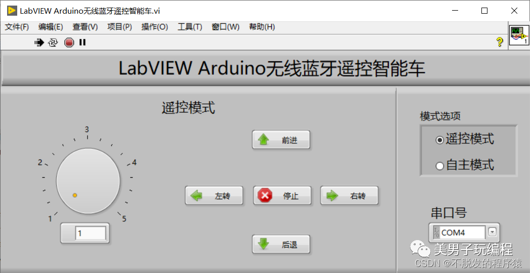
The LabVIEW front panel is divided into two parts: remote control mode and mode switching. The remote control mode part is used to control the running state of the car, including moving forward, backward, turning left, turning right, stopping, and speed adjustment; the mode selection part is used to switch between remote control mode and autonomous mode.
The LabVIEW host front panel for the wireless remote-controlled smart car is shown in the figure below:
6.2 Program Flowchart Design
The structure of the main LabVIEW host program is sequential structure + While loop + event structure. Firstly, the serial communication is initialized through the set serial port number; then, the program enters the While loop and event structure, continuously checking if there are events that need to be responded to and executed; the event structure includes “mode options”, “forward”, “backward”, “left turn”, “right turn”, “stop”, and “speed adjustment”. Finally, the serial communication is closed. In the program flowchart, we need to configure the serial port and send different commands through the serial port based on different key presses. The lower-level Arduino Uno receives the serial receipt, parses the command codes, and executes the corresponding commands.
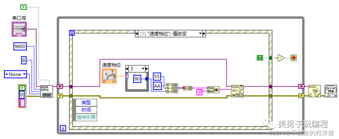
To better achieve communication, the following communication protocol is established: frame header + command code + operation code. 0x55 is the frame header, 0xAA is the remote control command, 0xFF is the autonomous command, with the remote control command operation codes: 0x00 for forward, 0x10 for backward, 0x20 for left turn, 0x30 for right turn, 0x40 for stop, 0x50 for speed level 1, 0x60 for speed level 2, 0x70 for speed level 3, 0x80 for speed level 4, 0x90 for speed level 5.
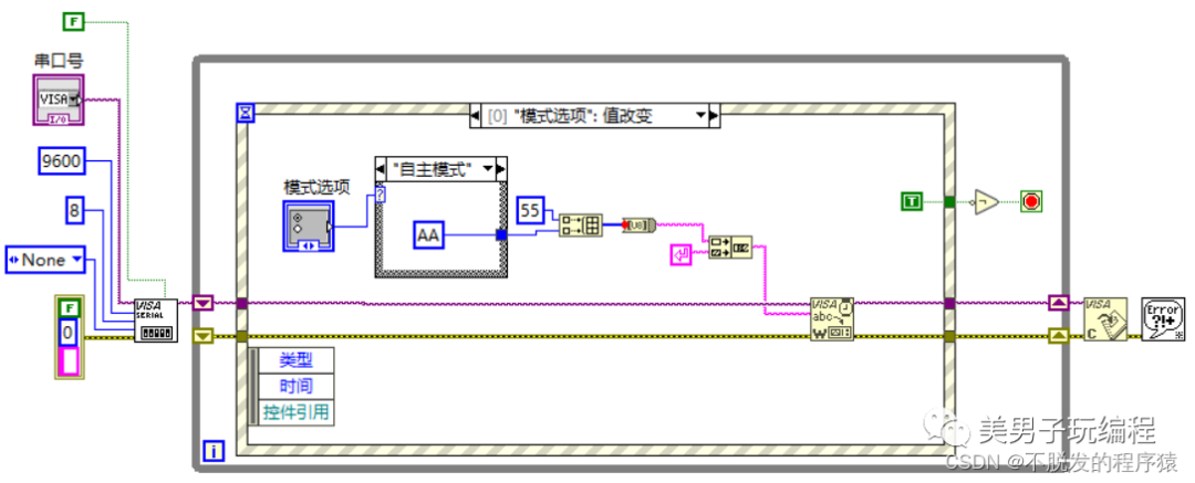
In the “mode options” event, the current selected mode is read, and 0x55AA and 0x55FF are sent to the Arduino controller, representing switching to remote control mode and autonomous mode, respectively. The program flowchart for the “mode options” value change event is shown in the figure below:
In the “forward” event, 0x55AA00 is sent to the Arduino controller via serial communication, setting both DC reduction motors to move forward. The program flowchart for the “forward” value change event is shown in the figure below:

In the “backward” event, 0x55AA10 is sent to the Arduino controller via serial communication, setting both DC reduction motors to move backward. The program flowchart for the “backward” value change event is shown in the figure below:
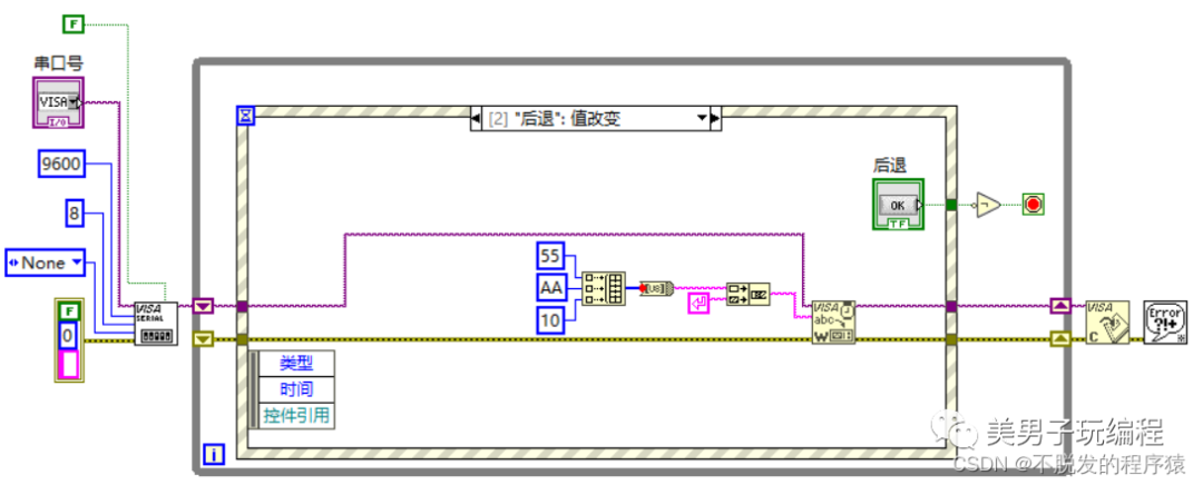
In the “left turn” event, 0x55AA20 is sent to the Arduino controller via serial communication, setting the right motor to move forward and the left motor to move backward, achieving a left turn. The program flowchart for the “left turn” value change event is shown in the figure below:
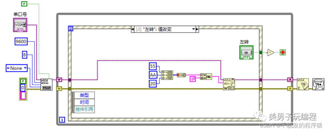
In the “right turn” event, 0x55AA30 is sent to the Arduino controller via serial communication, setting the right motor to move backward and the left motor to move forward, achieving a right turn. The program flowchart for the “right turn” value change event is shown in the figure below:
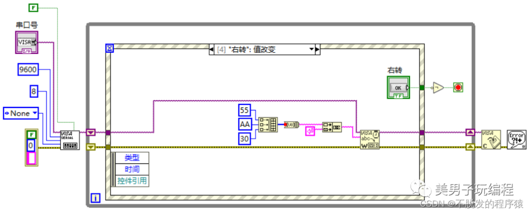
In the “stop” event, 0x55AA40 is sent to the Arduino controller via serial communication, setting both left and right motors to stop, thus stopping the car. The program flowchart for the “stop” value change event is shown in the figure below:
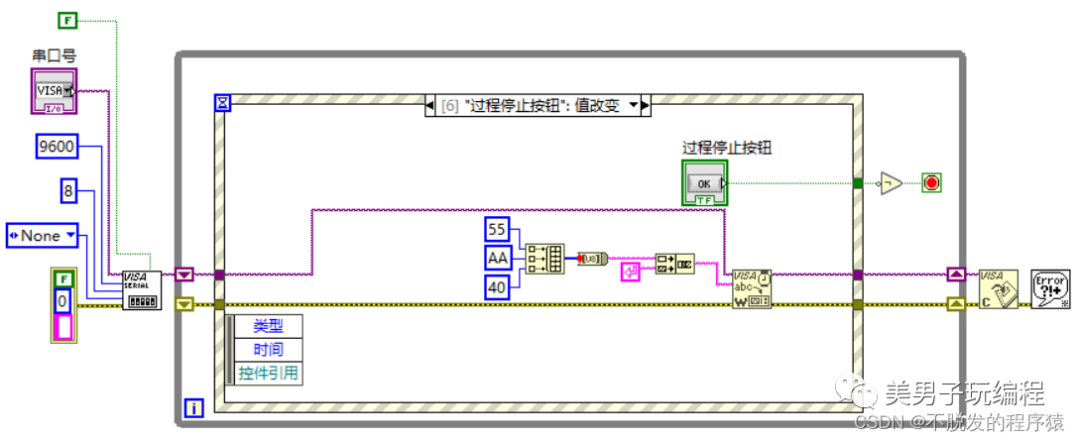
In the “speed level” value change event, the current selected speed level is read, and 0x55AA50, 0x55AA60, 0x55AA70, 0x55AA80, and 0x55AA90 are sent to the Arduino controller, representing low speed, medium-low speed, medium speed, medium-high speed, and high speed, respectively. The program flowchart for the “speed level” value change event is shown in the figure below:
 Previous Recommendations
-
Working with a 12-year-old to develop a maker project: How to drive an LED dot matrix module?
-
LabVIEW Image Features and Machine Vision Concepts (Theory Part – 4)
-
Jenkins Remote Publishing on Windows Server via SSH

