Author • Expert Truck Repair
Introduction to CAN Instrumentation
With the continuous development of commercial vehicles, their instrumentation has undergone significant changes, gradually moving towards electronic, digital, intelligent, and networked systems. As an important interface for information exchange between the driver and the vehicle, automotive instrumentation is currently evolving towards the CAN bus instrumentation stage.
The CAN network is one of the most widely used fieldbus forms internationally, developed by a German company to solve data conversion between modern vehicle controllers and testers. The CAN line facilitates information exchange among various automotive systems, forming a large closed-loop control system that includes automotive instrumentation, sensors, satellite positioning, and driving recorders. The CAN line offers a high transmission rate and strong anti-interference capabilities.
We all know that the function of CAN instrumentation is to record and display certain vehicle parameters while the vehicle is in operation, allowing the driver to understand the vehicle’s status in real time and adjust their driving habits based on the vehicle’s working conditions. During maintenance, technicians can also read the current fault codes from the CAN instrumentation, which helps in vehicle repairs.
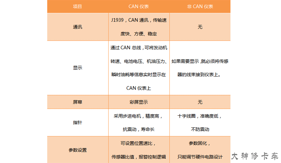
How does CAN instrumentation differ from traditional instrumentation, and what are its advanced features?
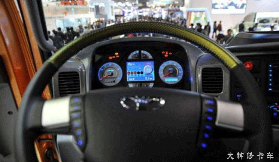
CAN Instrumentation Wiring
Although CAN instrumentation has added many functions and has a very fast transmission speed, the complex interface has also caused confusion among drivers to some extent. For example, what do the various indicator lights represent? Why does this one light up? What does it mean? How can I turn it off?
Therefore, this article will help you understand how to interpret CAN instrumentation!
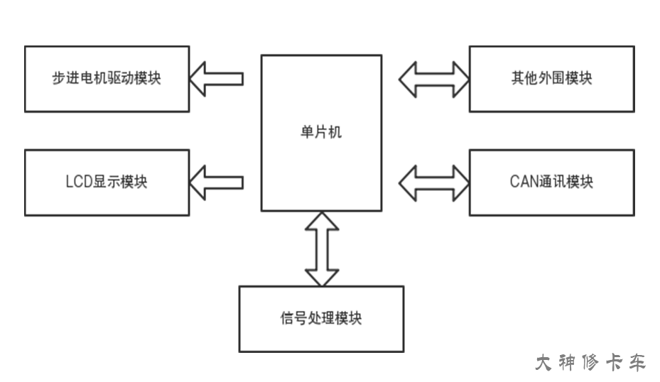
CAN instrumentation typically consists of several modules, including a controller (usually a microcontroller), signal processing module, LCD display module, CAN communication module, stepper motor driver module, and other peripheral modules.
Here, we will explain the pin definitions of the Dongfeng Tianlong Hercules instrumentation;
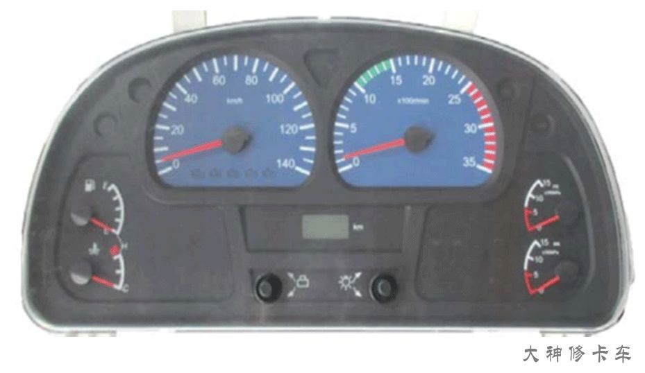
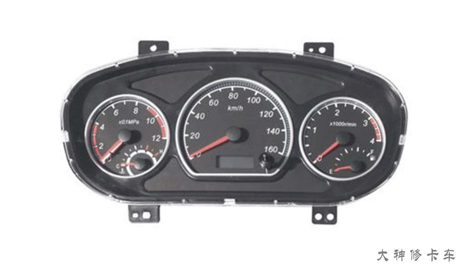
▲Hercules Instrumentation Appearance
This is a schematic diagram of the power supply, ground, and communication pins for Hercules instrumentation; we should remember these key pins.
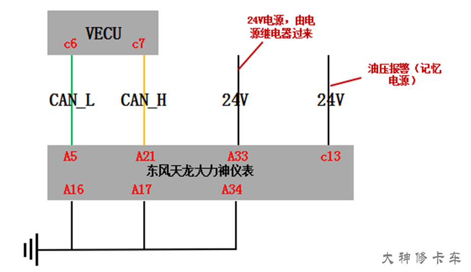
In fact, this instrumentation is somewhat similar to Bosch’s EDC17CV44/54 ECU, as both are divided into two plugs; however, for instrumentation, it has fewer pin connections. In the ECU, we refer to them as K plug and A plug, while in the instrumentation, we call them A plug and C plug.
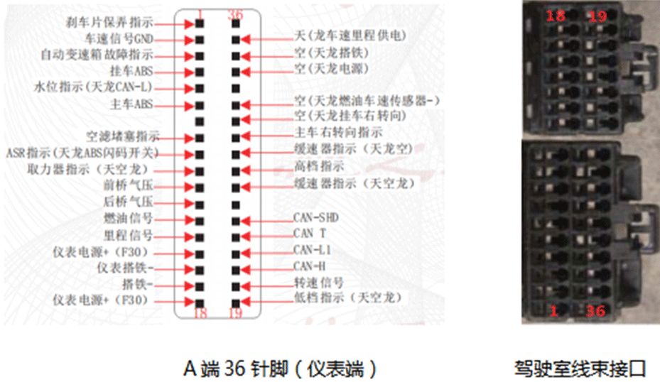
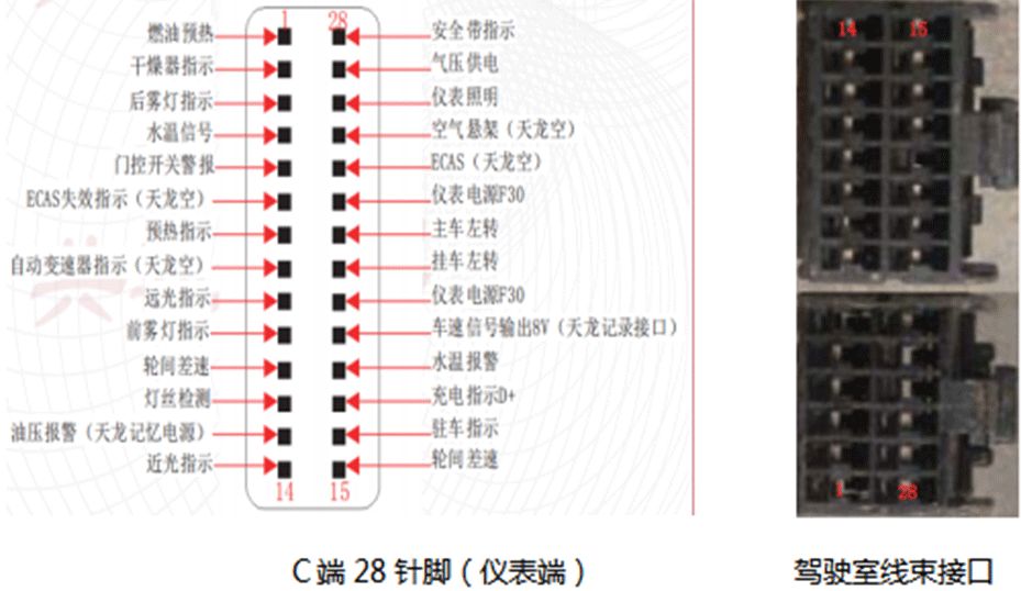
We can see from the pin definition diagram (instrumentation side) that the solid square represents the male plug, while the corresponding two images of the cab wiring harness connectors represent the female plug. When we unplug the connectors to check the pins, the pin definitions are reversed, so technicians should be careful not to make mistakes!
Fault Cases
If the instrumentation reports a fault related to the CAN line, it is generally TCO1, which indicates a fault with the instrumentation. Sometimes, the diagnostic tool will not specify what component TCO1 refers to, so technicians should remember this to avoid confusion in the future.
① Vehicle Configuration
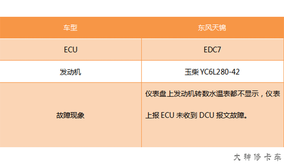
②Fault Analysis
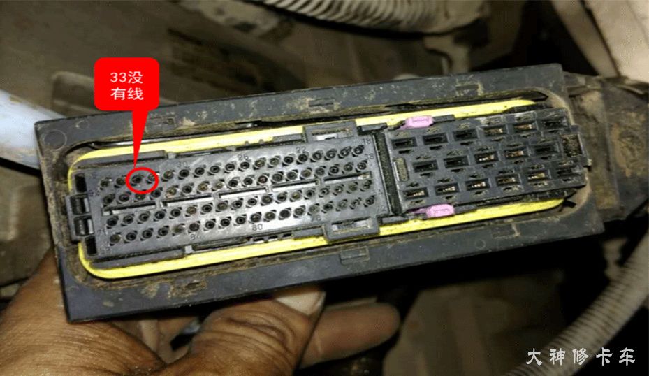
Unplug the ECU connector and find that pin 33 has no wire, indicating that the vehicle’s water temperature, speed, etc., are transmitted via the CAN line.
③Troubleshooting
(1) Read the fault codes, which show three faults:
0890:CAN communication error
0642:Indicator light 3 has no signal
0841:Main relay 2 shorted to ground
Reading the fault codes indicates that there is no issue with the CAN line from the ECU to the diagnostic interface.
(2) Analyze the fault codes and symptoms, concluding that the possible cause is a CAN line issue, such as open circuit, short circuit, or poor connection; ECU or instrumentation module problems, data anomalies; or interference from other CAN modules. Focus on checking the CAN line.
(3) Unplug the connectors from both the instrumentation and ECU ends, measure the wire harness continuity, and find no issues.
(4) Turn off the key, unplug the ECU end, and measure the resistance between CAN_H and CAN_L to be 120 ohms, indicating no issues.
(5) Plug in the ECU connector, measure the resistance between the CAN lines to be 60 ohms, which is normal! Measure the voltage to be around 2.8V, which is normal!
(6) Since no problems were found with the CAN line, suspecting ECU or instrumentation faults, we decided to replace parts for testing, replacing both the ECU and instrumentation, but the fault persisted, indicating that neither the ECU nor the instrumentation was the problem.
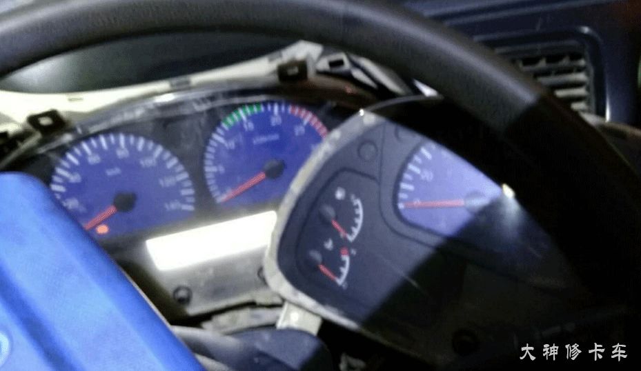
(7) Suspecting it was still a CAN line issue, we decided to do a flying wire test, cutting the green wire harness, and testing the vehicle; the instrumentation started showing water temperature and speed, indicating that the fault was in the green CAN_L line. Both voltage and resistance were normal, and the flying wire fault was resolved, so it must be a loose connection or poor contact, commonly found at the large connector.
(8) After inspection, we found that the contact at the pin of the green wire harness was poor, so we inserted a copper wire and tightened the screw, resolving the fault!
Fault Summary
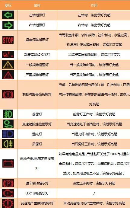
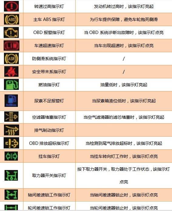
Finally, I would like to supplement some common indicator lights for everyone; I hope technicians take a screenshot so they won’t be caught off guard when they encounter them!
· The End ·
How to Understand Cummins Aftertreatment Data Flow?
Click to Watch

– Recommended Reading –
Click to Read the Article
● The Timing Fault That Drives Car Owners Crazy Has Been Solved by Me
● How the Diesel Engine Timing Synchronization Works So Cleverly?
● If the Vehicle Cannot Start and You Have Been to Two Repair Shops Without Resolving the Fault, What Should You Do?