1. Introduction
The previously made test circuit board for the STM32F373 did not have the 16-bit high-precision ADC pins exposed, so a new board was made to test the performance of the 16-bit ADC in the F373.
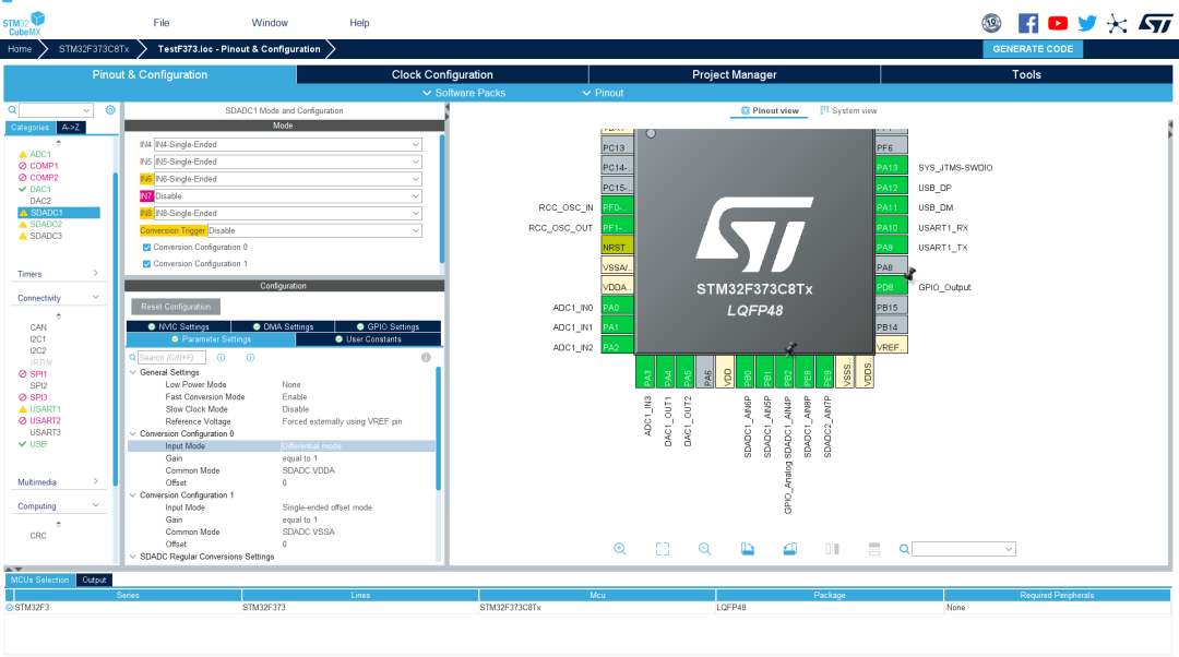
2. Designing the Circuit Board
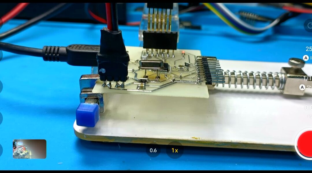
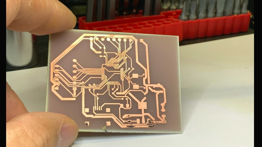
Based on the previous experimental circuit board, the original output pin header was connected to the high-precision 16-bit ADC pins. The wiring was redone, and the test circuit board was produced using a one-minute PCB fabrication method.

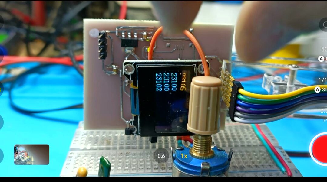
▲ Figure 1.2.1 Test Circuit Board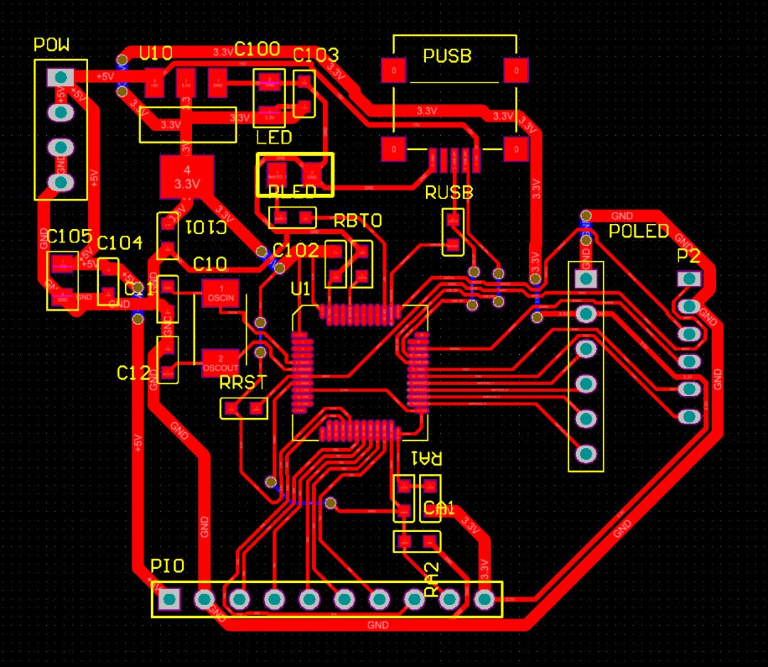
▲ Figure 1.2.2 PCB LayoutAfter one minute, the experimental circuit board was obtained, and it was made perfectly. After soldering and cleaning, the circuit board was debugged.
3. Software Testing
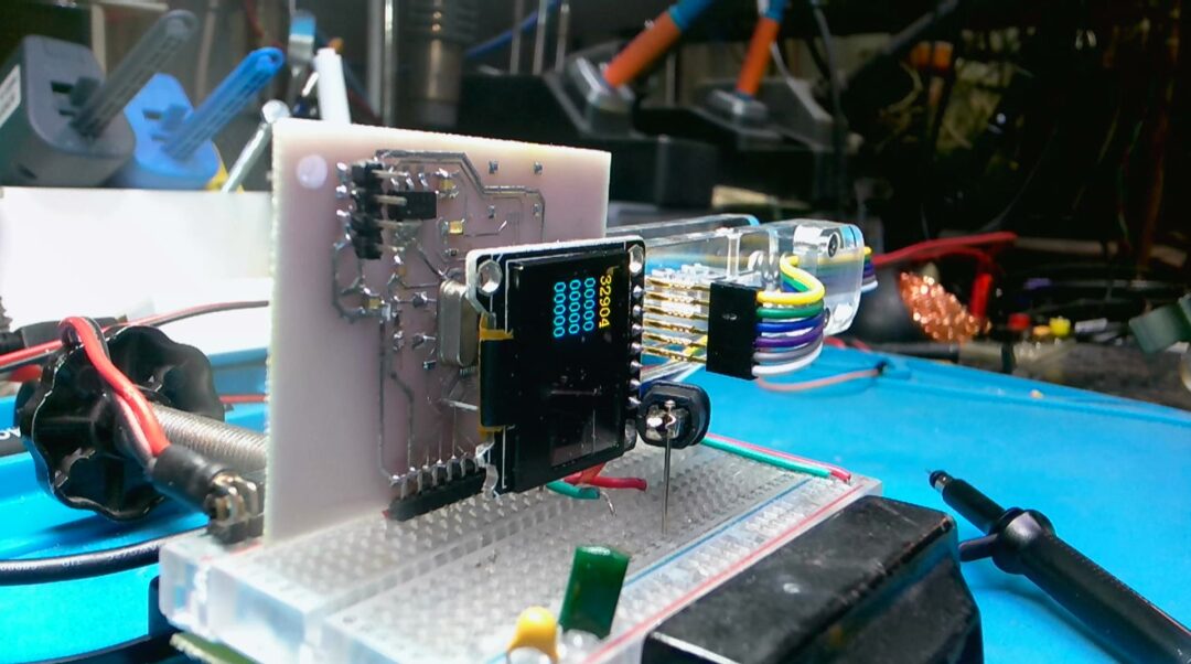
The test circuit was placed on a breadboard, and a working power supply of 5V was provided. After voltage regulation to 3.3V on the circuit board, the working power supply was provided to the microcontroller.
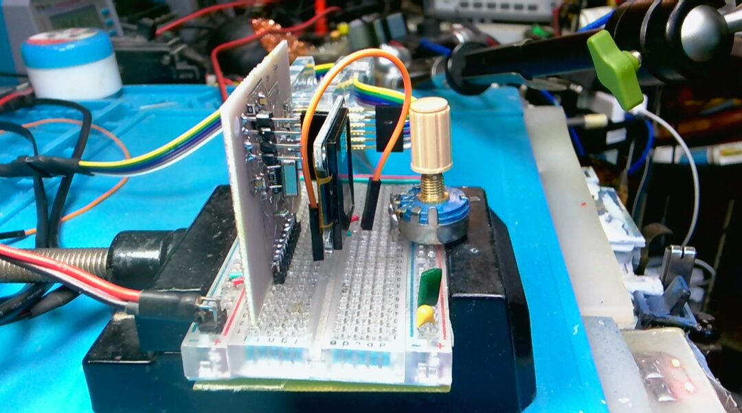
Using a potentiometer, different voltages were provided to input channel 4 of SDADC1, and the microcontroller displayed the collected values on the OLED screen. The collected values were observed to change. To obtain the input range of the ADC, a DH1766 programmable voltage source was used to set the input voltage. The collected values and corresponding voltages were recorded.
First, the Single Ended mode was tested, with a reference voltage of 3.3V from an external input. The ADC conversion voltage range is from 0 to 1.65V, with a maximum value of 0x7fff. The conversion mode was set to Single Ended Zero Reference, allowing the voltage conversion range to reach the reference voltage range, and the conversion results ranged from -0x8000 to 0x7fff.
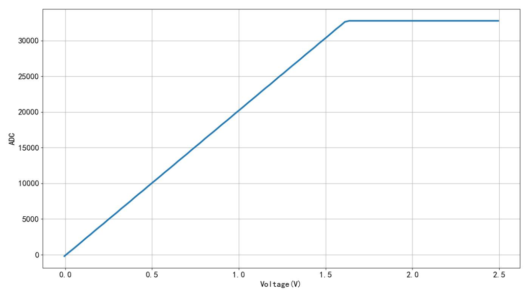
▲ Figure 1.3.1 Input Voltage and Conversion Results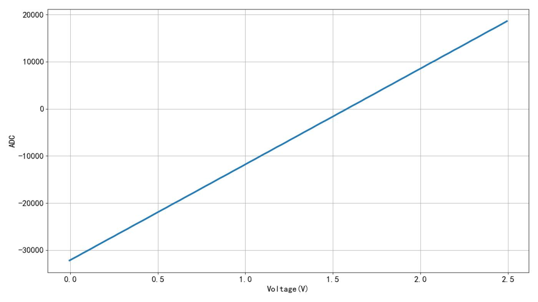
▲ Figure 1.3.2 Measurement Results Set to Single-End Zero Reference4. Conversion Speed
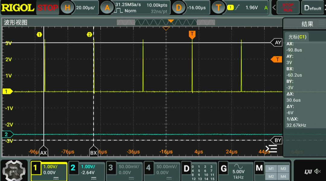
By setting the software, a pulse was output on the LED pin in the DMA interrupt. By measuring the pulse, the conversion rate of the ADC could be determined, which was approximately 11kHz. The conversion mode was set to fast mode, and upon re-measurement, the conversion speed was observed to reach around 33kHz.
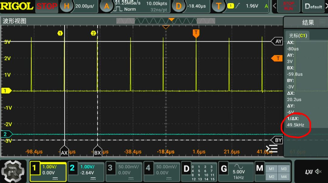
The system time was adjusted, and the clock of the Sigma Delta ADC was set to 6MHz, achieving the maximum operating clock frequency for this module. Upon re-measuring the speed of the ADC, it was observed to reach around 50kHz.
※ Conclusion ※
This article tested the 16-bit ADC in the STM32F373. The ADC can output 16-bit binary two’s complement conversion results. The maximum conversion speed can reach 50kHz.
USB Interface Applications in STM32F373: https://zhuoqing.blog.csdn.net/article/details/136089672
[2]ADC Functionality in STM32F373: https://zhuoqing.blog.csdn.net/article/details/136084829
[3]DAC Signal Generation Modes in STM32F373: https://zhuoqing.blog.csdn.net/article/details/136084445
[4]DAC Output Testing in STM32F373: https://zhuoqing.blog.csdn.net/article/details/136077591
[5]High-Frequency Voltage Output via UART: https://zhuoqing.blog.csdn.net/article/details/136076009
[6]Testing a Simple LED Blinking Program for STM32F373: https://zhuoqing.blog.csdn.net/article/details/136072748
[7]Developing STM32F373 Circuit Board Based on SWD: https://zhuoqing.blog.csdn.net/article/details/136071546