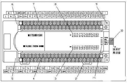
1. Meaning of Mitsubishi PLC Indicator Lights
① Input Indicator Light
The row of indicator lights marked with “IN” are the input signal indicator lights, as shown in Figure 3-1-3 “⑤”. Each indicator light corresponds to one input signal of the PLC. When there is a signal at the corresponding input terminal, the indicator light will illuminate; when there is no signal, the indicator light will turn off.
② Output Indicator Light
The row of indicator lights marked with “OUT” are the output signal indicator lights, as shown in Figure 3-1-3 “⑩”. Each indicator light corresponds to one output signal of the PLC. When there is a signal output at the corresponding output terminal, the indicator light will illuminate; when there is no signal output, the indicator light will turn off.
③ Model Mark
The “FX2N – 48 M R” in the PLC is the model marking, with the meanings of each part as follows:
① ②③④
① is the series name; ② is the total number of input and output points, where 48 means 24 input points and 24 output points; ③ is the type of unit, where M indicates a basic unit, E indicates a mixed input/output expansion module and expansion unit, EX indicates a dedicated input expansion module, and EY indicates a dedicated output expansion module; ④ indicates the output form, where R indicates relay output, T indicates transistor output, and S indicates thyristor output.
④ Operating Status Indicator Lights
There are four operating status indicator lights on the PLC. The indicator light marked “POWER” indicates the PLC power status; it lights up when the PLC is powered on. The indicator light marked “RUN” indicates the PLC running status; it lights up when the PLC is in operation. The indicator light marked “BATT.V” indicates low voltage of the internal lithium battery; it lights up when the battery voltage drops to a level that requires replacement. The indicator lights marked “PROG•E” and “CPU•E” are error indicators; when these lights flash, it indicates that there is an error in the program written into the PLC, and when these lights are constantly on, it indicates an error in the PLC’s internal CPU.
2. Diagnosing PLC Failures Based on Indicator Lights:
1. Is the POWER light on the panel not lit?
There is a “POWER” LED indicator light on the front of the main unit, I/O expansion base, I/O expansion module, and special module. When the main unit is powered on, the green LED light should be on. If the indicator light does not light up after powering on the main unit, please disconnect the wiring from the “24+” terminal. If the indicator light turns on normally, it indicates that the DC load of the FX2 is too high. In this case, do not use the DC power supply from the FX2 “24+” terminal; please prepare a separate DC 24V power supply.
If the indicator light still does not light up after disconnecting the wiring from the “24+” terminal, it is possible that the internal fuse of the PLC has blown. Please contact our local sales office, and we will handle it as soon as possible.
2. Is the POWER light flashing?
If the POWER light is flashing, it is likely that there is a short circuit between the “24+” terminal and the “COM” terminal. Please disconnect the wiring from the “24+” terminal. If the indicator light returns to normal, please check your wiring. If the indicator light continues to flash, it is likely that the POWER board inside the PLC has failed. Please return this PLC to our local sales office, and we will handle it as soon as possible.
3. Is the “BATT.V” LED light on?
When this red LED light is on, it indicates that the lithium battery inside the PLC is nearing the end of its life (approximately one month remaining). Please replace the lithium battery as soon as possible to avoid losing the program in the PLC (when using RAM).
If the LED light remains on after replacing the lithium battery, it is likely that the CPU board of this PLC has failed. Please return this PLC to our local sales office, and we will handle it as soon as possible.
4. Is the “PROG.E” LED light flashing?
Generally, when this red LED light is flashing, it is mostly due to unreasonable program logic. Another possible reason could be incorrect parameter settings or interference from external noise causing changes in the program content. If you are using a handheld programmer (FX-20P-E), it is recommended to check D8004, and then check D8060 to D8069 based on the content of D8004. From D8060 to D8069, you can obtain a data value, which is the error code. For details on the error code, please refer to the “Mitsubishi Programmable Controller Programming Manual!”
5. Is the “CPU.E” LED light on?
When the “CPU.E” LED light is on, it may be caused by one of the following reasons:
(1) Conductive dust has entered the PLC.
(2) The scanning time of the PLC exceeds 100ms (check D8012 to know the longest execution time).
(3) The RAM/EPROM/EEPROM memory card was removed while powered on.
(4) There is noise interference near the PLC.
If the above issues are ruled out and the “CPU.E” LED light remains on, this PLC may indeed be faulty. It is recommended to return it to us so we can help identify the cause.
Frequently Asked Questions:
What should I do if my PLC has been set with a password?
If you have the original program, you can simply erase all the memory of the PLC. The method to clear is as follows:
a. If you are using a handheld programmer
After connecting the programmer to the PLC, select ONLINE mode, press the GO key, and the screen will prompt you to enter the password. At this time, press the SP key 8 times, then press the GO key 3 times. This will restore your PLC to factory settings, and you can then re-enter the original program into the PLC.
b. If you are using FXN, DOS version V2.0 or above software
In the MODE window, press 7, 5, 3, then select “MEMORY ALL CLEAR” from the options that appear using the up and down keys, and press the “Enter” key. This will clear all internal memory of the PLC. The user can then write the original program into the PLC.
c. If you are using FXN Windows version V1.0 or above software
First, display the original program on the screen, set the PLC to STOP status, then select PLC from the function selection column on the screen, and choose PLC memory clear… After a new screen appears, check all three options, then press the “Enter” key. A screen will appear with “Confirm” and “Cancel” options for you to decide. At this time, you should select “Confirm” and press the “Enter” key! If this screen disappears, it indicates that the PLC has been restored to factory settings, and you can re-enter the program.