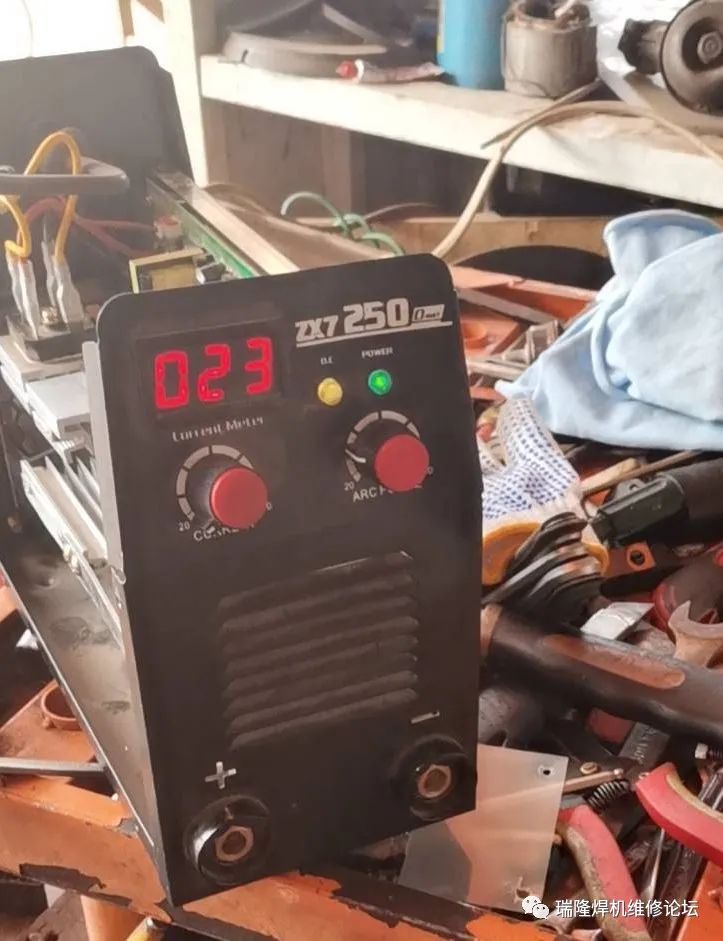
This machine was repaired with the assistance of one of our students, who reported that the machine had no no-load voltage. This is a single-phase 220 single board IGBT machine.
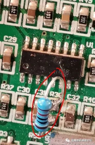
We first disconnected the high voltage and applied 310V. We measured the drive waveform of the tube using an oscilloscope and found none. Next, we measured the 11 and 14 pins of the 3525 and found no voltage. Then we measured the voltages at pins 8 and 9, both around 4.5V, which is normal. When we measured the sawtooth wave at pin 5 of the 3525, we found that the resistance at pin 6 was missing, possibly knocked off. Since we did not have the schematic for this machine, we did not know the value of that resistor. We first measured the capacitor at pin 5 to be 2nF and assumed the inverter frequency of the welder to be 35kHz. We used the following formula (the frequency of the sawtooth wave at pin 5 of the 3525) to backtrack the value of this resistor. The sawtooth wave frequency at pin 5 of the 3525 is twice the inverter frequency of the welder.

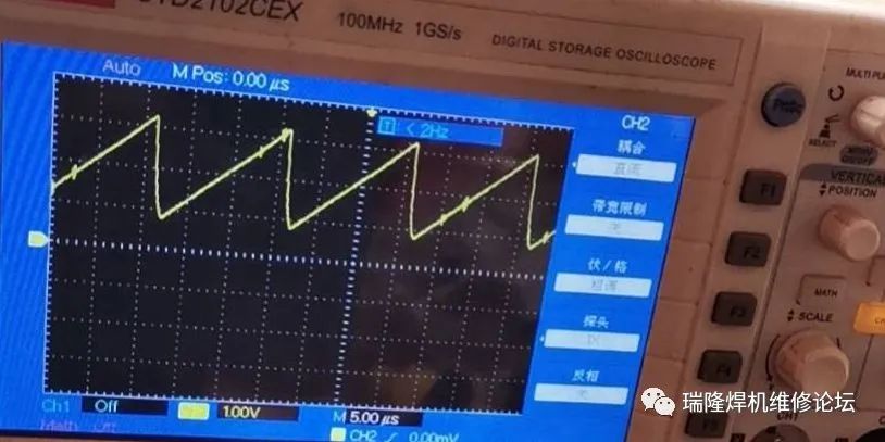
The machine f is 70kHz, RD is 0, CT is 2nF. We calculated that the RT at pin 6 of the 3525 is around 10.2K. After soldering a 10K resistor, we measured the waveforms at pin 5 of the 3525 and the drive waveform of the IGBT, which are shown below, and both are normal.
The sawtooth wave at pin 5 of the 3525 is as follows:
The drive waveform of the IGBT is as follows:
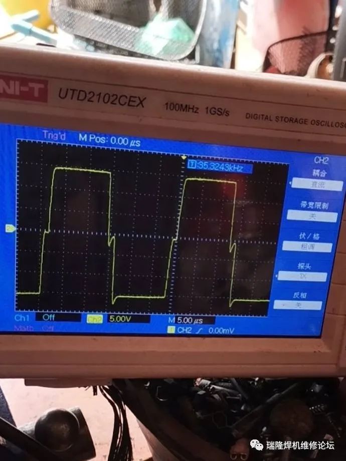
After confirming that there were no issues with the low voltage, we measured the no-load voltage of the high voltage at 59V, and the welding current was adjustable.
Repair Commentary: During the repair of the control board, we often encounter some components that are damaged, but without schematic data, we do not know the parameters of the components, which makes repairs challenging. With a clear understanding of the control principles, one can backtrack the parameters or replace specific component parameters.