In the field of industrial automation, continuous physical quantities such as temperature, pressure, and flow need to be transmitted to the PLC throughanalog signals, which are then converted into actual engineering values. This article dissects the essence of conversion from an engineer’s perspective, using examples from mainstream brands like Siemens, Mitsubishi, and Omron, to help you fully grasp the principles and practical applications in just 5 minutes.
1. Analog Signals: The “Translator” from Sensors to PLC
Analog signals are continuous electrical signals, with the most commonly used in industry being the4-20mA current signal (which is resistant to interference and can transmit over long distances) and the0-10V voltage signal (suitable for short distances). Sensors convert physical quantities (such as temperature) into standard signals, and the PLC’s analog module then converts these into digital values (e.g., 0-27648). This conversion from “signal to digital” is the core of the calculation.
Key Parameter Comparison (A must-remember for beginners)
The digital range of different brand PLCs varies significantly, directly affecting the conversion results. It is recommended to take a screenshot for reference:
| Brand / Series | 4-20mA Digital Range | 0-10V Digital Range | Typical Module Model |
|---|---|---|---|
| Siemens S7-1200/300 | 5530-27648 | 0-27648 | SM1231 AI4x13bit |
| Mitsubishi FX Series | 800-4000 | 0-4000 | FX3U-4AD |
| Omron CJ Series | 0-4000 | 0-4000 | CJ1W-AD041-V1 |
Engineer Experience: In the 4-20mA range, “4mA” is the “live zero point,” which can indicate a broken wire (0mA indicates a fault). It is more reliable than 0-20mA, so current signals should be prioritized on-site.
2. Universal Conversion Formula: Calculate Actual Values in 3 Steps
The core formula (linear mapping principle, just remember this one):Actual Value = (Digital Value – Digital Lower Limit) / (Digital Upper Limit – Digital Lower Limit) × (Physical Upper Limit – Physical Lower Limit) + Physical Lower LimitSymbol Explanation:
- Digital Value: The raw value read by the PLC (e.g., AIW256)
- Digital Upper and Lower Limits: The digital range corresponding to the module’s signal (see the table above)
- Physical Upper and Lower Limits: The sensor’s range (e.g., temperature sensor 0-100℃)
Example 1: Siemens S7-1200 Temperature Conversion
Scenario: 4-20mA temperature sensor (range 0-100℃), PLC reads digital value = 16384, find the actual temperature.Known: Digital lower limit = 5530, digital upper limit = 27648, physical lower limit = 0℃, physical upper limit = 100℃Substituting into the formula:Actual Temperature = (16384 – 5530) / (27648 – 5530) × (100 – 0) + 0 ≈ 49.5℃
Example 2: Mitsubishi FX3U Pressure Conversion
Scenario: 0-10V pressure sensor (range 0-1MPa), PLC reads digital value = 2000, find the actual pressure.Known: Digital lower limit = 0, digital upper limit = 4000, physical lower limit = 0MPa, physical upper limit = 1MPaSubstituting into the formula:Actual Pressure = (2000 – 0)/(4000 – 0)×(1 – 0) + 0 = 0.5MPa
3. 3 Diagrams to Address Practical Pain Points
1. Signal → Digital → Actual Value Flowchart
This clearly shows the entire conversion process. Save this diagram for a clear understanding of the conversion logic:
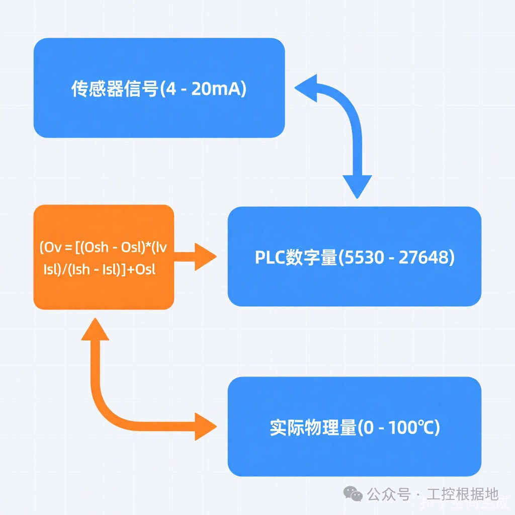
Key Point: The A/D conversion of the module is the “unsung hero”; for example, Siemens SM1231 converts 4-20mA to 1-5V voltage through a 250Ω resistor, and then converts it to a digital value through a 13-bit ADC.
2. Two-Wire Sensor Wiring Diagram (A must-see on-site)
4-20mA sensors are mostly two-wire; incorrect wiring can lead to signal loss. Follow the diagram:
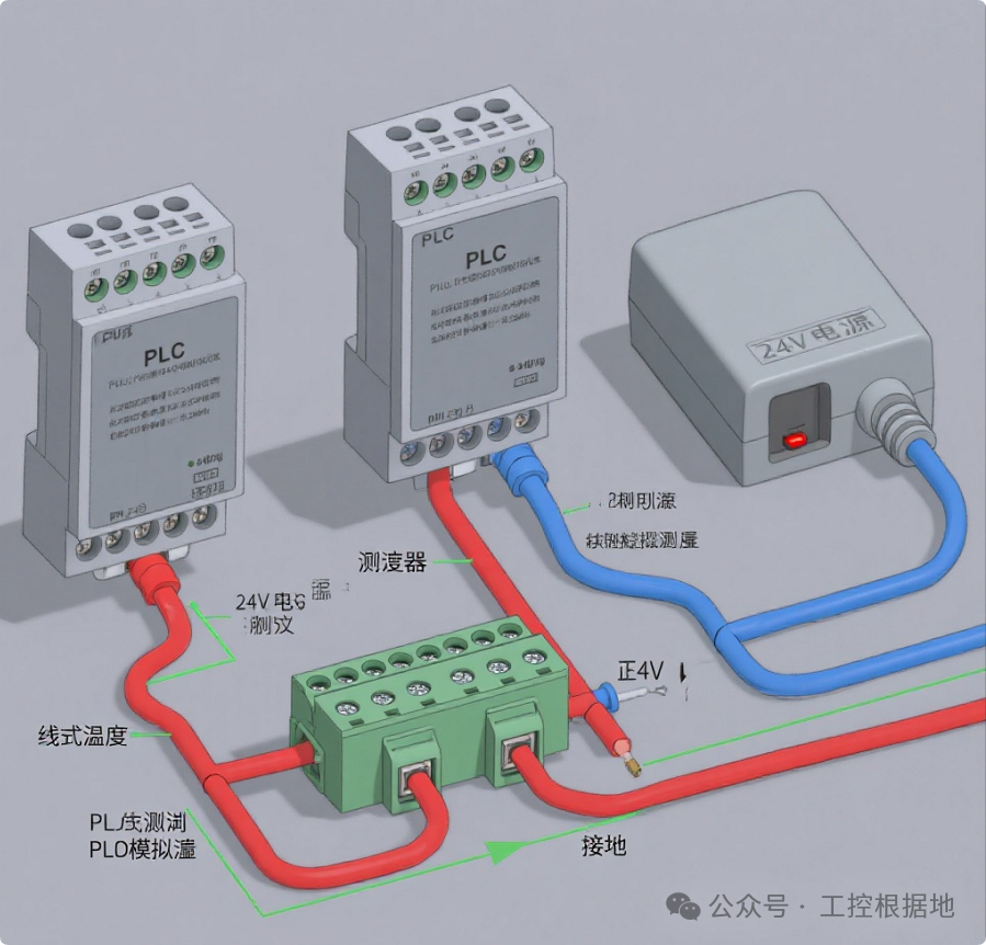
Wiring Mnemonic: Power positive → Transmitter positive, Transmitter negative → PLC AI+, PLC AI- → Power negative, Shielding layer grounded at one end (PLC cabinet side).
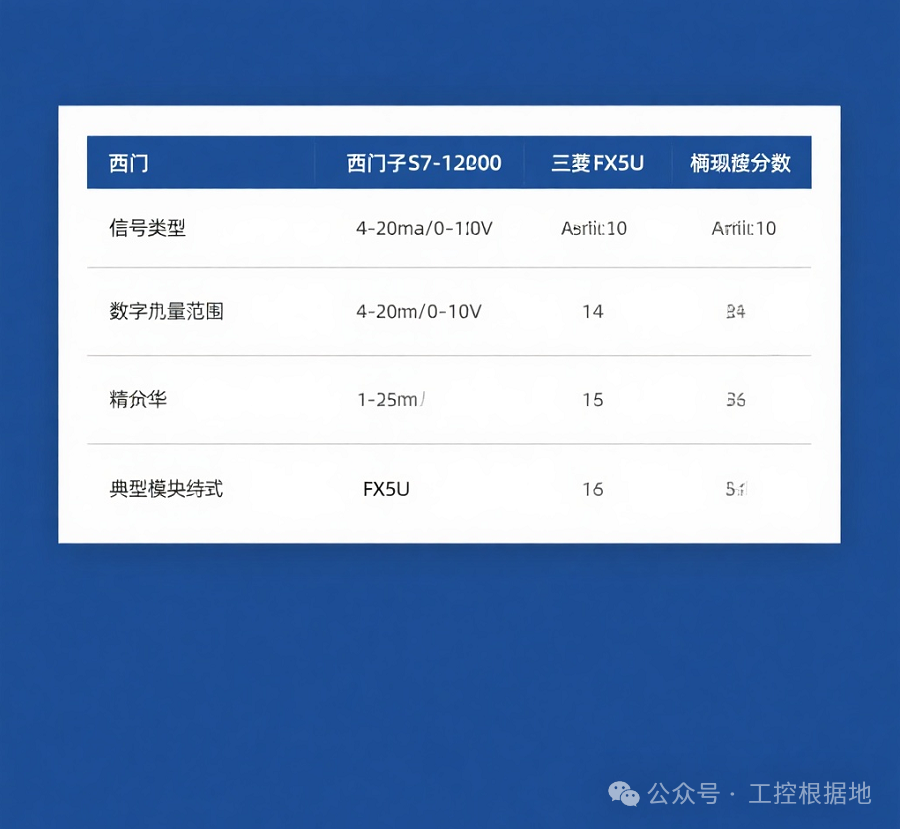
3. Brand Parameter Comparison Table (To avoid pitfalls)
The digital range varies significantly between brands; always verify before conversion:
-
Don’t overlook the “Offset” in Siemens 4-20mA corresponds to 5530-27648; if you directly use 0-27648 for calculations, it will result in negative values at 4mA. You must strictly deduct the lower limit of 5530.
-
Mitsubishi FX5U Register Quick Reference The analog input values are in D6020 (Channel 1), D6060 (Channel 2), and the output values are written to D6180, without complex programming.
-
3 Key Elements for Wiring Anti-Interference
- Use twisted shielded cables, length ≤ 100 meters
- Avoid strong interference sources like inverters and motors
- Unutilized channels in multi-channel modules should be shorted (e.g., short 0+ and 0- in Siemens SM1231)
Use “Current Source Method” for Signal Verification During on-site debugging, use a 4-20mA signal generator to connect to the module. If the digital value deviates from the theoretical value by >1%, check the module configuration (e.g., whether the range card is set to “4-20mA”).
Reverse Use of Formula to Calculate Output Value When controlling valve openings, if the target physical quantity is known (e.g., 50% opening = 5mA), you can backtrack the digital value: Digital Value = (Target Value – Physical Lower Limit) / (Physical Upper Limit – Physical Lower Limit) × (Digital Upper Limit – Digital Lower Limit) + Digital Lower Limit.
5. Summary: 3 Core Steps to Master in 5 Minutes
- Identify the Signal: Confirm the sensor output type (4-20mA/0-10V) and check the PLC module’s digital range (reference table).
- Apply the Formula: Substitute into “Actual Value = (Digital Value – Lower Limit) / Range × Physical Range + Lower Limit” and quickly calculate using a calculator.
- Verify the Result: 4mA corresponds to the physical lower limit, 20mA corresponds to the upper limit, and 12mA should be in the middle (e.g., 50℃ when the range is 0-100℃). If the deviation exceeds 5%, check the wiring or module configuration.
Remember: The essence of analog value conversion is “linear mapping.” Practice with 2 examples (Siemens + Mitsubishi), and you will be able to operate independently within 5 minutes!

Like, share, and spread the word!