The installation and debugging of PLC control systems involve various tasks that must be performed in sequence. Each step is interconnected, and any oversight can lead to debugging failures, resulting in project delays or even equipment damage. This article presents the technical experiences summarized from on-site practices regarding the installation and debugging of PLC control systems, and discusses common installation and debugging issues encountered on-site, along with proposed solutions.
1. System Installation and DebuggingProperly arranging the installation and debugging procedures is key to ensuring the efficient and high-quality completion of these tasks.1.1 Preliminary Technical PreparationThe more thorough the technical preparation before system installation and debugging, the smoother the installation and debugging process will be. The preliminary technical preparation includes the following:(1) Familiarize yourself with the technical documentation and original materials provided with the PLC, deeply understand its performance, functions, and various operational requirements, and develop operational procedures.(2) Gain a comprehensive understanding of the design documentation and the system’s process flow, especially the control requirements for each production device. Based on this understanding, draw process flow diagrams, interlock diagrams, system function diagrams, and system operation logic flowcharts, which will aid in a deep understanding of the system’s operational logic and is an important part of the preliminary technical preparation.(3) Familiarize yourself with the performance, design, and installation status of each process device, especially the control and power wiring diagrams of each device, and compare them with the actual equipment to identify and correct errors promptly.(4) Based on a comprehensive understanding of the design scheme and PLC technical documentation, compile a list of PLC input and output point numbers (including an overview of internal coils, I/O locations, corresponding devices, and the functions of each I/O point).(5) Study the programs provided in the design documentation, and for complex logical parts, draw timing diagrams for input and output points. Some logical errors in the design can be identified during the drawing of timing diagrams.(6) Develop debugging plans for subsystems, and then integrate them into a comprehensive system debugging plan based on group discussions.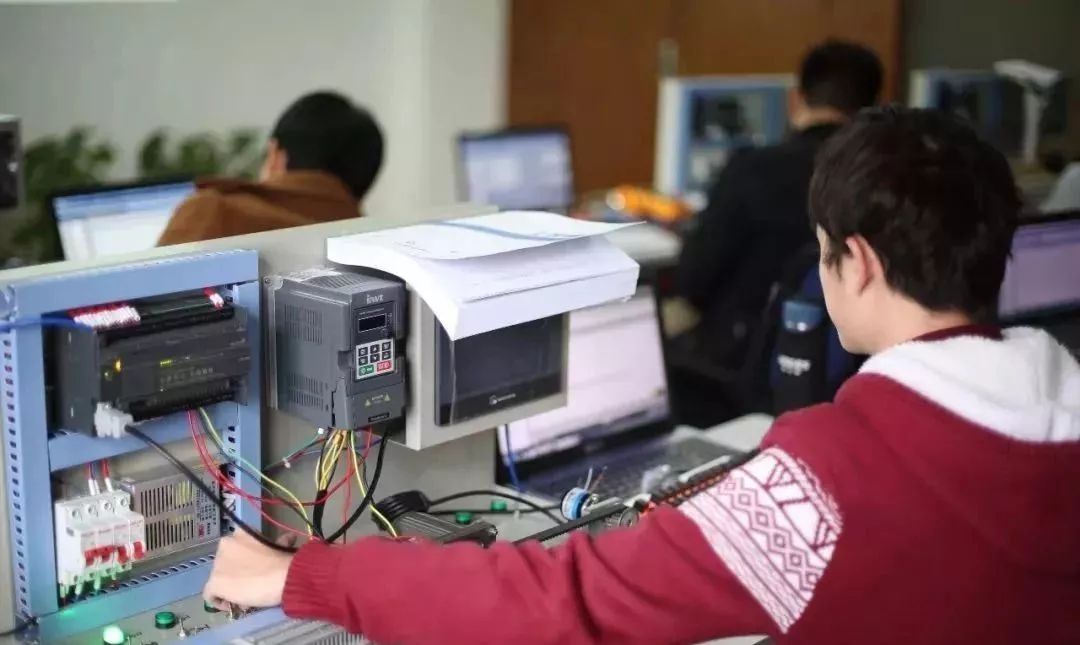 1.2 PLC InspectionThe inspection should be conducted jointly by both parties to confirm the model, quantity, specifications, and performance of the equipment, spare parts, technical documentation, and accessories, which should be verified during laboratory and on-site debugging. The inspection results should be documented and signed by both parties.1.3 Laboratory Debugging(1) The laboratory installation and commissioning of the PLC involves creating a metal frame to secure the input and output modules of each workstation, connecting each station to the host, programmer, printer, etc., using coaxial cables according to the installation guidelines. After checking the wiring for correctness and ensuring that the power supply voltage matches the PLC voltage selection, follow the startup procedure to power on, load the system configuration tape, confirm the system configuration, and load the programming tape, following the operational procedures to activate the system, at which point various operational tests can be conducted.(2) Input the working program.(3) Simulate I/O inputs and outputs, checking and modifying the program. The purpose of this step is to verify the correctness of the input working program, whether the logic expressed by the program matches the interlock relationships of the process equipment as per the design control requirements, and whether the program runs smoothly. If there are discrepancies or if the process cannot be completed, it indicates that the program is incorrect and needs modification. During this process, understanding of the program will gradually deepen, preparing for on-site debugging, and also allowing for the identification of unreasonable and incomplete parts of the program for further optimization.There are two debugging methods: ① Simulation method: Create a debugging board according to the design, using toggle switches to simulate input nodes and small relays to simulate the relays and contactors of the production process equipment, with auxiliary contacts simulating the return signal nodes during equipment operation. The advantage is the realism of the simulation, which can reflect whether logical misoperations occur when the mechanical contacts in the field and the electronic contacts in the PLC are interconnected, given their differing switching speeds. The disadvantage is that it increases debugging costs and some debugging workload.② Forced method: Utilize the PLC’s forced function to force the program’s mechanical contacts (switches) involved in the field to be “on” or “off,” thereby forcing the program to run. The advantage is that it reduces debugging workload and is simple, without additional costs. The disadvantage is that logical verification is not comprehensive, and manually forcing the simulation of field nodes “on” or “off” can cause the program to run discontinuously, only allowing for segmented operation.Based on our on-site debugging experience, we adopt the simulation method for some important field nodes and the forced method for the rest, complementing each other’s strengths. During the logical verification phase, it is essential to fill out a debugging work log daily, including the names of debugging personnel, time, debugging content, modification records, faults and their resolutions, and handover acceptance signatures, to establish a debugging work responsibility system and retain first-hand materials of the debugging process. For any modifications to the design program, they should be noted on the design drawings, and the designer’s opinions should be sought promptly to accurately reflect the design requirements.1.4 On-Site Installation and Inspection of PLCAfter completing laboratory debugging and when conditions are suitable, the equipment should be moved to the installation site. During installation, ensure that the plugs are securely inserted and fastened with bolts; communication cables should be of a uniform model and not mixed; if necessary, use instruments to check the signal attenuation of the lines, ensuring that the attenuation does not exceed the indicators specified in the technical documentation; measure the insulation resistance to ground of the host, I/O cabinets, and connecting cables; measure the grounding resistance of the system’s dedicated grounding; check the power supply, etc., and keep records. Only after confirming that all items meet the requirements can power be turned on.1.5 On-Site Wiring, I/O Points, and Signal Inspection and AdjustmentCheck and confirm the correctness of the control circuit and main circuit wiring of each process device on-site, and conduct individual tests in manual mode; check all input points entering the PLC system (including toggle switches, buttons, relay and contactor contacts, limit switches, and instrument position debugging switches, etc.) and their connections to the PLC input modules, repeatedly operating them to confirm their correctness;Check all relays, contactor coils, and other actuators receiving PLC outputs and their connections to the output modules to confirm their correctness; measure and record their circuit resistance and insulation resistance to ground. If necessary, power the output circuit according to the output node’s power voltage level to ensure that the output circuit is not short-circuited; otherwise, when the output point powers the output circuit, it may burn out the module due to a short circuit.
 Generally, medium and large PLCs can also receive and output analog signals if equipped with analog input and output modules. In this case, it is necessary to check the primary detection or transmission components that deliver analog input signals to the PLC, as well as the adjustment or execution devices that receive the PLC’s analog output, to confirm their correctness. If necessary, input analog quantities to the detection and transmission devices to verify their installation correctness and whether the output analog quantities meet the standards required by the PLC; send the same analog signal as the PLC’s analog output signal to the receiving adjustment or execution components to check whether they can operate normally. PLCs equipped with analog input and output modules can monitor the process parameters (analog quantities) during production, perform calculations and adjustments according to the predetermined model in the design scheme, and implement process control of the production process.This step is crucial, and the inspection and adjustment process is complex and tedious, requiring serious attention. As long as all external process equipment is intact, all external nodes entering the PLC are correct, reliable, and stable, and all wiring connections are accurate, along with correct program logic verification, the linkage debugging can be successfully completed in one go, achieving a significant effect with minimal effort.1.6 System Simulation Linkage TestThe purpose of this test is to place the PLC and logic program that have undergone laboratory debugging into the actual process flow, conducting logical verification of the system operation through the input and output nodes and connecting lines of the on-site process equipment.During the test, disconnect the main circuit of the process equipment controlled by the PLC (only keeping one phase for relay control power supply) to prevent it from rotating when powered on. According to the design requirements, conduct system simulation experiments for different operating modes and other control functions of the subsystem, confirming the correct positions of each toggle switch, operating mode selection switch, and other preset switches. Then, start the system through the PLC, observing and recording the engagement and disengagement of the relays and contactors corresponding to each PLC output node, as well as their sequence, time intervals, and signal indications to ensure they align with the design’s process flow logic control requirements, and observe and record the operational status of other devices.For executing mechanisms that cannot operate during the simulation linkage test, such as material level switches, limit switches, and the switch quantities of instruments, and their interlocks with other subsystems, use manual assistance, external inputs, or internal forced methods to simulate as needed, to assist the PLC in commanding the entire system to operate according to the design’s logical control requirements.1.7 Individual Testing of PLC-Controlled EquipmentThe purpose of this test is to confirm whether the PLC output circuit can drive the relays and contactors to operate normally, thus enabling the equipment to run, and to check whether the return signals from the operating equipment can be correctly sent to the PLC input circuit, and whether the limit switches can operate normally.The method is to use the PLC to force the output nodes corresponding to a specific process device (motor, actuator, etc.) to operate the relays and contactors, causing the equipment to run. At this time, observe and record the operational status of the equipment, checking whether the return signals from the equipment and the actions of the limit switches and actuators are correct.During the test, special attention should be paid to ensuring that the forced device is marked with a danger indication sign, and a dedicated person should be assigned to monitor it. The PLC operator should only force the device to start after receiving instructions from the monitoring personnel. It is crucial to emphasize that during the entire debugging process, without sufficient preparation, the use of forced methods to start the equipment is strictly prohibited to ensure safety.1.8 System No-Load Linkage Test Under PLC ControlThe purpose of this test is to confirm whether the process equipment that has undergone individual no-load testing can operate correctly according to process requirements after being connected to the PLC, which has been proven to have correct logic through system simulation testing, and whether the signal system is correct, verifying the reliability and stability of each external node. Before the test, a no-load linkage test plan should be developed, discussed, and confirmed, and strictly executed according to the plan. During the test, first conduct linkage tests for subsystems, using manual assistance (node short-circuiting or forced methods) for subsystem interlocks, and then conduct full system linkage tests. The test content should include various start-stop and operating modes required by the design, as well as stopping under accident and emergency conditions, and various signals. In summary, as much as possible, anticipate scenarios to better align with actual on-site conditions. Accident scenarios can be simulated using forced methods, and the settings for accident points should be determined based on process requirements.Before conducting the linkage load test, a comprehensive check of the entire system must be performed again, and training for the operating personnel should be conducted to ensure the success of the system linkage load test on the first attempt.2. Discussion on Signal Attenuation Issues(1) The maximum signal attenuation from the PLC host to the I/O station is 35dB. Therefore, careful planning should be done before laying cables, drawing a cable layout diagram, and minimizing cable length (for every additional 1km, signal attenuation increases by 0.8dB); minimize the use of splitters (each splitter causes a signal attenuation of 14dB) and cable joints (each joint causes a signal attenuation of 1dB).(2) It is best to lay communication cables in a single bus manner, meaning that a unified communication trunk connects to the I/O stations through splitters, rather than in a star or radial layout. The number of I/O stations on both sides of the PLC host and the transmission distances should be as consistent as possible to ensure good network impedance matching.(3) Splitters should be placed as close to the I/O stations as possible to reduce interference.(4) The ends of communication cables should connect to 75Ω resistors as BNC cable terminators, and when disconnecting cables from the I/O cabinets, the 75Ω terminator should be connected to one end of the cable network to maintain good matching.(5) The distance between communication cables and high-voltage cables should be at least 40cm/kV; when crossing high-voltage cables, they must cross perpendicularly.(6) Communication cables should avoid being laid parallel to AC power lines to reduce interference from AC power. Similarly, communication cables should be kept away from large motors, welding machines, and large inductors.(7) Cable laying should avoid high-temperature areas and areas prone to chemical corrosion.(8) When laying cables, leave a margin of 0.05%/°C to accommodate thermal expansion and contraction requirements.(9) All cable joints, splitters, etc., should be tightly connected and secured with screws.(10) When stripping the cable outer skin, avoid damaging the shielding layer. When cutting the metal core and insulator, use wire strippers, and avoid scratching or damaging the center conductor.3. Discussion on System Grounding Issues(1) The grounding of the main unit and the upper parts of each branch station should be connected together using 10mm² braided copper wire and connected to a separate grounding network, ensuring it is separated from the low-voltage grounding network to avoid interference. The system grounding resistance should be less than 4Ω. A 3mm thick rubber pad should be placed between the PLC host and each screen and cabinet to provide insulation, and bolts should also be insulated.(2) The grounding of I/O station equipment should be connected to a shared grounding network using a separate grounding wire.(3) The shielding layer of communication cables should be gathered at the I/O processing module side of the PLC host and connected to the system’s dedicated grounding network, while the I/O station side should not be grounded. The grounding of cable joints should also be connected to the dedicated grounding network through the cable shielding layer. It is particularly important to ensure that the cable shielding layer does not have two-point grounding forming a closed loop, as this can easily cause interference.(4) The power supply should be isolated, meaning that the neutral line of the power supply should be floating. When unbalanced current occurs, it will directly enter the system’s neutral point through the neutral line of the power supply, rather than forming a loop through the protective grounding, which could interfere with PLC operation.(5) The grounding of I/O modules should be connected to the neutral line of the power supply.4. Issues to Note During Debugging(1) Before connecting the system, configuration must be performed, determining the number of I/O points managed by the system, the number of input registers, holding registers, communication ports and their parameters, the matching of I/O stations, and their scheduling methods, as well as the size of the logical area occupied by users, etc. Once the configuration is confirmed, the system will operate according to certain constraints. If reconfiguration is needed, the program generated based on the original configuration will not run under the new configuration, otherwise, it will cause system confusion. Therefore, the first configuration must be done carefully, leaving room for I/O stations, I/O point numbers, register numbers, channel port numbers, and user storage space, considering recent developments. However, the settings for I/O stations, I/O point numbers, register numbers, and port numbers will occupy a certain amount of memory, while extending the scan time and reducing the operating speed. Therefore, the margin cannot be too large. It is particularly important to note that the running system must not be reconfigured.(2) For medium and large PLCs, since the CPU scans the program in segments, updating the status of I/O points after each segment is completed, this greatly improves the system’s real-time performance. However, if the program is not segmented properly, it may also lead to reduced real-time performance or slower operating speeds. Different segmentations will significantly affect the program’s running time, especially for particularly long individual program segments. Generally speaking, the ideal program segmentation is for each segment to have approximately equal lengths.ConclusionThe installation and debugging of PLC control systems is a systematic project that requires orderly steps to ensure successful debugging. This article is merely a summary of the author’s experiences verified on-site. The PLC installation and debugging processes described herein have been applied in a series of technical transformations within enterprises, shortening construction periods and achieving successful debugging on the first attempt, resulting in satisfactory outcomes.
Disclaimer: This article is a network reprint. If there are any copyright issues, please contact for removal!