This section introduces the basic knowledge of microcontroller programming, following the previous discussions on why C language is used for microcontroller programming and the programming environments required. The first topic to cover is bitwise operations. Bitwise operations are very common when configuring the registers of a microcontroller. For example, when configuring a GPIO of a microcontroller as an output direction and setting it to 0, bitwise operations are very convenient.
Bitwise Operations in Microcontrollers
What operations are included in bitwise operations? There are six common operations: bitwise AND “&”, bitwise OR “|”, bitwise NOT “~”, bitwise XOR “^”, left shift “<<”, and right shift “>>”, as shown in the table below:
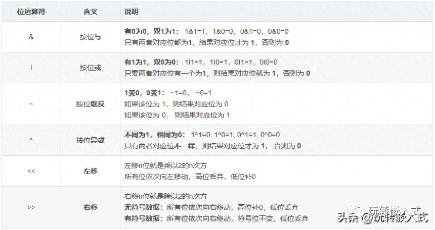
Bitwise Operations Table
Bitwise AND “&” Logic
The logic of bitwise AND “&” is that if there is at least one 0 in the inputs, the output is 0; the output is 1 only when all inputs are 1. The truth table is as follows:
|
Input A |
0 |
0 |
1 |
1 |
|
Input B |
0 |
1 |
0 |
1 |
|
Output |
0 |
0 |
0 |
1 |
Bitwise OR “|” Logic
The logic of bitwise “|” is that if there is at least one 1 in the inputs, the output is 1; the output is 0 only when all inputs are 0. The truth table is as follows:
|
Input A |
0 |
0 |
1 |
1 |
|
Input B |
0 |
1 |
0 |
1 |
|
Output |
0 |
1 |
1 |
1 |
Bitwise NOT (~) Logic
Bitwise NOT (~) can be understood as negation, meaning to flip the bits. When the input is 0, the output is 1; when the input is 1, the output is 0. The truth table is as follows:
|
Input |
0 |
1 |
|
Output |
1 |
0 |
Bitwise XOR “^” Logic
Bitwise XOR (^) is used to determine if the inputs are the same. If both inputs are the same, the output is 0; if the inputs are different, the output is 1. The truth table is as follows:
|
Input A |
0 |
0 |
1 |
1 |
|
Input B |
0 |
1 |
0 |
1 |
|
Output |
0 |
1 |
1 |
0 |
Left Shift “<<” and Right Shift “>>” Logic
When performing shift operations, it is important to consider whether the data is signed. In microcontroller programming, unsigned types are used more frequently, so here we will discuss unsigned shifting.
When unsigned data is left-shifted, zeros are filled in on the right, and the leftmost bits are discarded.
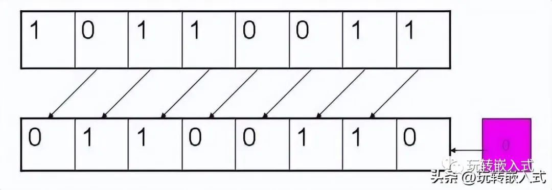
Left Shift “<<” Illustration
When unsigned data is right-shifted, zeros are filled in on the left, and the rightmost bits are discarded.
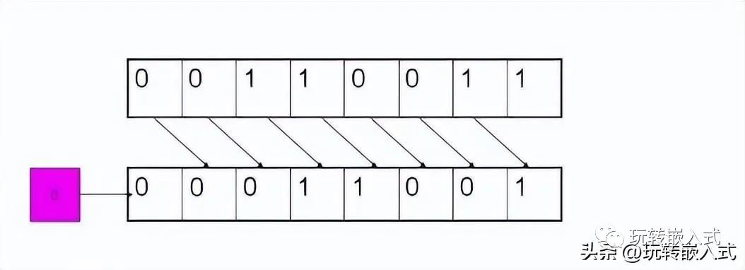
Right Shift “>>” Illustration
Significance of Bitwise Calculations
As mentioned earlier, bitwise logical calculations are very convenient for configuring registers because registers can be manipulated at the bit level. When performing operations on specific bits of a register, it is essential not to change the values of other bits.
Further discussions on the programming implementation of bitwise operations will follow.

Why Use C Language for Microcontroller Programming
What are the C Language Programming Environments for Microcontrollers
Do You Understand the Working Principle of IGBT?
After 10 Years in R&D, I Finally Understood My Mentor’s Words