USB, short for <span>Universal Serial Bus</span>, has long been an indispensable technology in our daily lives. From connecting keyboards and mice to PCs to enabling communication between embedded devices and hosts, USB has revolutionized peripheral connectivity with its simplicity and robust compatibility.
The Birth of USB
Let’s take a look at the PC usage scenario over 20 years ago: printers used parallel ports, mice connected via serial ports, and keyboards required dedicated interfaces, resulting in a desk cluttered with various odd connectors. Not to mention the hassle of IRQ settings and jumper switches every time a new device was installed, which was a nightmare for users. The birth of USB was aimed at solving these pain points.
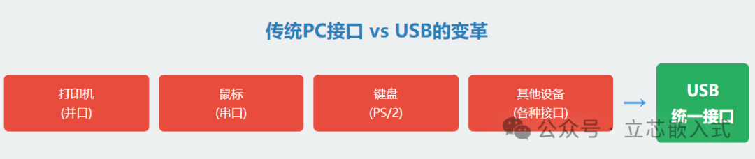
It not only freed PC users from the hassle of numerous connectors but also provided laptop manufacturers with a compact peripheral interface solution. More importantly, USB significantly reduced the number of cables and adapters for external devices through a unified protocol and power design, making desktops much tidier. Although USB seems commonplace today, it was a revolution in the field of PC peripherals back then.
For those of us in embedded development, USB is equally significant. Any device connected to a PC is essentially an embedded system. In the past, we relied on RS-232 or parallel ports for communication, but these interfaces have nearly disappeared from modern PCs, making USB the mainstream choice. Whether developing a USB data acquisition device or upgrading the interface of an old product, dealing with USB is inevitable.
The Hardware Foundation of USB
The core of USB is a serial communication protocol, with data transmitted over a pair of differential signal lines, and another pair responsible for power supply. Despite having just these four wires, the design of USB is quite sophisticated.
Cables and Connectors
The USB standard defines two types of cables: high-speed at 12Mbps and low-speed at 1.5Mbps. High-speed cables have better shielding and are slightly more expensive. In terms of connectors, USB uses Type A and Type B connectors to distinguish upstream and downstream; Type A connects to the host or upstream device, while Type B connects to peripherals or downstream devices. The two connector shapes are different, making it impossible to plug them in incorrectly, which is a thoughtful design.
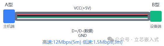
However, there are limitations on cable length: a maximum of 5 meters for high-speed mode and 3 meters for low-speed mode. This may sound counterintuitive, but high-speed mode uses higher quality cables, resulting in less signal attenuation, allowing for longer lengths.
Topology Structure
The connection method of USB is called a hierarchical star topology. The host (usually a PC) contains a root hub that manages all peripherals. The hub acts like a switch in a network, expanding connection ports and allowing more devices to connect. The host is the master of the entire system, responsible for scheduling communication, while peripherals are the slave devices that follow commands.
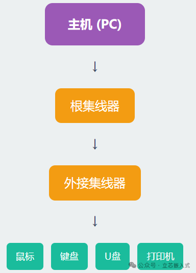
Each time a peripheral connects, the host communicates with the device through an enumeration process, inquiring about its identity, assigning an address, and loading drivers. This process is fully automated, eliminating the hassle of manually setting addresses or IRQs. The hub can also detect device insertion and removal, dynamically adjusting the network topology, allowing users to hot-swap devices while the system remains stable.
Peripherals are divided into two types: single-function devices (like mice) and composite devices (such as cameras with audio). Hubs themselves are also considered peripherals, some with independent power supplies to power downstream devices, while others draw power from upstream, providing great flexibility.
USB Communication Mechanism
USB communication occurs between the host and the endpoints of the peripherals. An endpoint is an independently addressable data source or receiver within a peripheral, with each endpoint having a 4-bit address, plus direction and transfer type information. Endpoint 0 is dedicated to control transfers, while the remaining can support up to 15 bidirectional endpoints.
Communication occurs through virtual pipes, which connect the host and endpoints, similar to water pipes in a home, with each pipe having its own bandwidth and transmission characteristics. Endpoints return descriptors to inform the host of their configuration, such as transfer type, packet size, bandwidth requirements, etc. The host establishes pipes based on this information to ensure smooth communication.
USB supports four types of transfer, each with unique purposes:
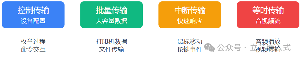
- Control Transfer: Used for device configuration, initialization, and command interaction, such as exchanging information during enumeration. It includes CRC checks and retransmission mechanisms to ensure data accuracy.
- Bulk Transfer: Suitable for transferring large volumes of data that are not time-sensitive, such as printers and scanners. Bulk transfer utilizes idle bandwidth, offering high cost-effectiveness, and also includes CRC protection.
- Interrupt Transfer: Don’t be misled by the name; this is not a CPU interrupt, but rather the host periodically polls the device to check for data. It is suitable for scenarios requiring quick responses with small data volumes, such as mice and keyboards, and includes error checking.
- Isochronous Transfer: Designed for audio and video streaming, where data is time-sensitive and prioritized for bandwidth usage. There is no error checking, as occasional packet loss is tolerable.
Host Driver
Goodbye to the simple days of RS-232; the complexity of USB makes driver development less user-friendly. The host side is usually a PC running Windows, and driver support directly impacts the development experience.
USB Driver Support in Windows
Windows manages USB drivers using WDM (Windows Driver Model), employing a layered architecture:
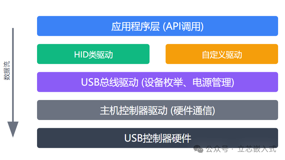
- Application Layer: Interacts with drivers through API calls, allowing developers to operate devices using file handles, which is simple and efficient.
- Class Driver or Custom Driver: Class drivers are for standard devices (like HID class for mice and keyboards) and are provided by Windows, eliminating development worries. Custom drivers are for non-standard devices, such as data acquisition systems, which require manual coding.
- USB Bus Driver and Host Controller Driver: Responsible for device enumeration, power management, and hardware communication, all handled by Windows, so developers don’t need to worry.
The good news is that if your device complies with the HID class standard, Windows’ built-in drivers can be used directly, saving a lot of time.
Core Components of Embedded USB
To master embedded USB development, one must understand the core components of the USB system.

1. Host
USB is a host-controlled bus, and the host is the core brain of the entire system. Its responsibilities include:
- Detecting device connections (like the click sound when a USB drive is plugged in).
- Identifying device types and loading corresponding drivers.
- Managing data transmission to ensure smooth communication.
For example, it’s like your home Wi-Fi router, which needs to know whether the connected device is a phone or a computer to allocate appropriate bandwidth.
2. Device (Peripheral)
A USB device is a functional module, such as a USB drive, keyboard, or camera. Each device communicates with the host through pipes, and the host identifies devices through the enumeration process. This process is somewhat like a teacher taking attendance, confirming each student’s presence before class can begin.
3. Class Driver
A class driver is a software module that implements specific functions, such as Mass Storage or CDC (Communication Device Class). The host uses class drivers to manage device interfaces. For instance, when you plug in a USB drive, the host knows it’s a storage device through the mass storage class driver, allowing it to read and write data. Both the host and device sides require corresponding class drivers, just like both parties need to have WeChat installed for a video call.
4. Controller
The USB controller is responsible for the physical connection between the host and the device. The controller driver is used to initialize the hardware, ensuring it can respond to system software commands. In simple terms, the controller is like an Ethernet cable, and the driver is the configuration that makes the cable work properly.
USB may seem complex, but once you grasp the concepts, you can navigate it with ease. Whether you are involved in embedded development, hardware communication, or simply want to ensure your device connects smoothly to a computer, USB is an area you cannot overlook. In future articles, we will share more in-depth USB development details, such as enumeration process analysis, descriptor design, and how to quickly get USB devices running on STM32. See you in the next article!