Infrared remote control is a commonly used communication method. Among the various encoding methods for infrared remote controls, the NEC protocol is widely used.
The characteristics of the NEC protocol are as follows:
The representation of logical 1 and logical 0 is shown in the figure below:
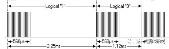
As can be seen, the bit time for logical 1 is 2.25ms, and the pulse time is 560us; the bit time for logical 0 is 1.12ms, and the pulse time is 560us.
A complete NEC data packet is as follows:
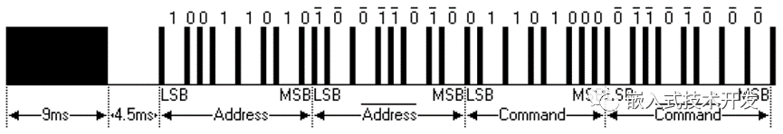
The first transmission is a 9ms high level + 4.5ms low level, which is the guide code.
Next is the 8-bit address code + the 8-bit inverse address code + the 8-bit command code + the 8-bit inverse command code.
The above is a normal data packet, but there may be a situation: when a key is long pressed, a repeat code is sent with a period of 110ms, as shown in the figure below:
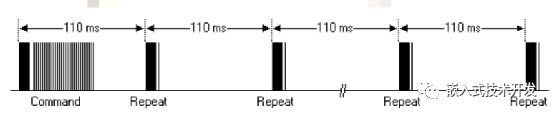
The repeat code consists of a 9ms high level and a 2.25ms low level, along with a 560us high level.
2. Decoding Program
In the above figure, it can be seen that the bit times for logical 1 and logical 0 are different, and the duty cycles are also different. Therefore, we can decode based on the length of the bit time or based on the different duty cycles (1/2 or 1/4), or both can be used as decoding conditions. Here we introduce decoding based on bit time.
It should be noted that many infrared integrated receivers improve sensitivity by outputting an inverse low level when inputting a high level.
The following figure shows a set of data captured by an oscilloscope:

uint32_t TIM3_Over_Cnt = 0;//TIM3 overflow countuint32_t TIM3_Sum_Cnt = 0;//Time interval between two falling edgesuint32_t cnt0 = 0;uint8_t IR_Data[60];void TIM3_IRQHandler(void){ /* USER CODE BEGIN TIM3_IRQn 0 */ /* USER CODE END TIM3_IRQn 0 */ // HAL_TIM_IRQHandler(&htim3); /* USER CODE BEGIN TIM3_IRQn 1 */ if(__HAL_TIM_GET_FLAG(&htim3, TIM_FLAG_UPDATE)) //Timer overflow interrupt { __HAL_TIM_CLEAR_FLAG(&htim3, TIM_FLAG_UPDATE); //Clear interrupt flag TIM3_Over_Cnt++; } cnt0 = __HAL_TIM_GET_COUNTER(&htim3); TIM3_Sum_Cnt = (TIM3_Over_Cnt << 16) + cnt0;//Get the value of the counter __HAL_TIM_SetCounter(&htim3,0);//Reset the counter TIM3_Over_Cnt = 0;//Reset the overflow count if (__HAL_TIM_GET_FLAG(&htim3, TIM_FLAG_CC1) != RESET)//TIM3CH1 capture interrupt { if(StartRevFlag == 1)//Received guide code, start decoding { if(TIM3_Sum_Cnt > 36000)//Greater than 36ms means end { RevComplete = 1;//Decoding complete IR_Tick = 0; } else if(RevComplete == 0) { if(TIM3_Sum_Cnt > 1000 && TIM3_Sum_Cnt < 1300)//1ms~1.3ms considered low level IR_Data[IR_Idx] = 0; else if(TIM3_Sum_Cnt > 2100 && TIM3_Sum_Cnt < 2400)//2.1ms~2.4ms considered high level IR_Data[IR_Idx] = 1; else //Receiving error, restart StartRevFlag = 0; IR_Idx++; if(IR_Idx > 59) IR_Idx = 59; } } else { if(TIM3_Sum_Cnt > 13000 && TIM3_Sum_Cnt < 14000)//13~14ms guide code { StartRevFlag = 1; } IR_Tick = 0; RevComplete = 0;//Decoding complete flag reset IR_Idx = 0;//Valid decoding bits TIM3_Over_Cnt = 0; TIM3_Sum_Cnt = 0;//Reset timer count } __HAL_TIM_CLEAR_IT(&htim3, TIM_IT_CC1); } /* USER CODE END TIM3_IRQn 1 */}The decoding program determines whether it is a guide code or logical 1 or logical 0 based on the interval between each captured falling edge. After receiving the guide code, it starts saving the decoded data, and finally determines the end of decoding based on the duration as well. There is no check for repeat codes here; those interested can add it themselves.
void IR_Rev(){ uint8_t num = IR_Idx / 8; uint8_t IRValue[8]; if(RevComplete == 1 && StartRevFlag == 1 && IR_Tick > 20) { if(num > 7) num = 7; for(uint8_t j=0;j<num;j++)//Combine each bit of decoded data into byte data { for(uint8_t i = 0;i< 8;i++) { IRValue[j] = IRValue[j]>>1; if(IR_Data[j*8+i]) IRValue[j] |= 0x80; } } if(IRValue[0] == 0x00 && IRValue[1] == 0xFF)//Address code correct { switch(IRValue[2])//Determine data code { case 0x46: KeyValue = S_key_Menu; break; case 0x43: KeyValue = S_key_Set; break; case 0x40: KeyValue = S_key_Rst; break; case 0x15: KeyValue = S_key_Down; break; case 0x09: KeyValue = S_key_Up; break; } } StartRevFlag = 0; RevComplete = 0; IR_Tick = 0; }
END
Source: Embedded Technology Development
→ Follow to avoid getting lost ←