Click the “Mechanical and Electronic Engineering Technology” above to follow us
Gas sensors are the core of gas detection systems, typically installed within the detection head. Essentially, a gas sensor is a converter that transforms the volume fraction of a specific gas into a corresponding electrical signal. The detection head conditions the gas sample through the gas sensor, which usually includes filtering out impurities and interfering gases, drying or cooling treatment, sample suction, and even chemical treatment of the sample to enable faster measurements by the chemical sensor.
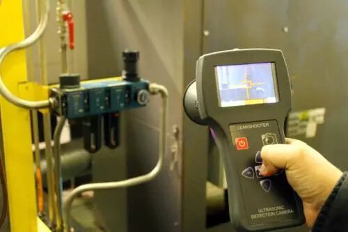
There are many types of gases with various properties, and thus, there are many types of gas sensors. Based on the nature of the gas to be detected, they can be classified into: sensors for detecting flammable and explosive gases, such as hydrogen, carbon monoxide, natural gas, and gasoline vapors; sensors for detecting toxic gases, such as chlorine, hydrogen sulfide, and arsine; sensors for detecting gases in industrial processes, such as oxygen in steelmaking furnaces and carbon dioxide in heat treatment furnaces; and sensors for detecting atmospheric pollution, such as NOx, CH4, and O3 that contribute to acid rain, as well as household pollutants like formaldehyde. Based on the structure of gas sensors, they can be divided into dry and wet types; based on the output of the sensor, they can be divided into resistive and non-resistive types; and based on the detection methods, they can be divided into electrochemical, electrical, optical, and chemical methods.
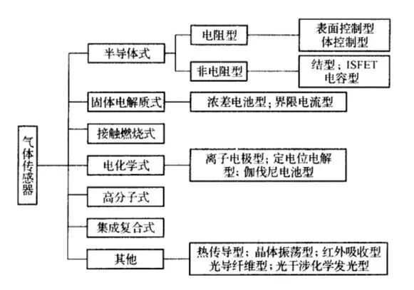
Semi-conductor Gas Sensors
Semi-conductor gas sensors can be divided into resistive and non-resistive types (junction type, MOSFET type, capacitive type). The principle of resistive gas-sensitive devices is that gas molecules cause a change in the resistance of the sensitive material; non-resistive gas-sensitive devices mainly include M()s diodes and junction diodes as well as field-effect transistors (M()SFET), which utilize the principle that sensitive gases change the MOSFET’s turn-on voltage, similar to the principle structure of ISFET ion-sensitive devices.
Resistive Semi-conductor Gas Sensors
Operating Principle
It has been found that materials such as SnO2, ZnO, Fe2O3, Cr2O3, MgO, and NiO2 exhibit gas sensitivity. Gas-sensitive films made from these metal oxides are impedance devices, where gas molecules can exchange ions with the sensitive film, undergoing reduction reactions that cause changes in the resistance of the sensitive film. As a sensor, this reaction must also be reversible, meaning that to eliminate gas molecules, an oxidation reaction must also occur. The heater within the sensor aids in the oxidation reaction process. SnO2 film gas-sensitive devices are currently mainstream products due to their good stability, ability to operate at lower temperatures, capability to detect various gases, and mature technology. Additionally, Fe2O3 is also widely used and researched. Besides the traditional SnO, SnO2, and Fe2O3 categories, a batch of new materials has been developed, including single metal oxide materials, composite metal oxide materials, and mixed metal oxide materials. The research and development of these new materials have significantly improved the characteristics and application range of gas sensors.
Selective sensitivity is a key performance of gas sensors. For example, SnO2 films are sensitive to multiple gases, and improving the selectivity and sensitivity of SnO2 gas-sensitive devices has been a focus of research. Major measures include: adding different noble metals or metal oxide catalysts to the substrate material, setting appropriate operating temperatures, and using filtering devices or permeable membranes to filter sensitive gases externally. Doping SnO2 materials is a primary method to improve sensor selectivity; adding Pt, Pd, Ir, and other noble metals can effectively enhance the sensitivity and response time of the device, and different catalysts lead to different adsorption tendencies, thereby improving selectivity. For instance, doping noble metals Pt, Pd, and Au in SnO2 gas-sensitive materials can enhance sensitivity to CH4, while doping Ir can reduce sensitivity to CH4, and doping Pt and Au can enhance sensitivity to H2, while doping Pd can reduce sensitivity to H2.
The operating temperature affects the sensitivity of the sensor. The left image below shows the resistance characteristics curve of SnO2 gas-sensitive devices at various gas temperatures. As seen from the graph, the device’s sensitivity to various gases differs at different temperatures, and this characteristic can be utilized to identify gas types.
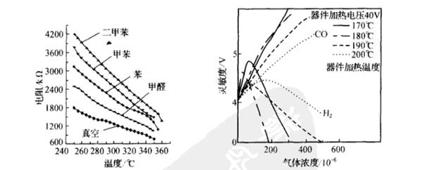
The preparation process also significantly impacts the gas-sensitive characteristics of SnO2. For example, adding ThO2 to SnO2 and changing the sintering temperature and heating temperature can produce different gas sensitivity effects. By mass calculation, adding 3-5% ThO2 and 5% Sm2 to SnO2 and sintering at 600°C in a H2 atmosphere can create thick film devices with an operating temperature of 400°C, which can serve as CO detection devices. The right image above shows the characteristics of gas-sensitive devices sintered at 600°C. It can be seen that within the operating temperature range of 170-200°C, the sensitivity curve for H2 is parabolic, while changing the operating temperature has little effect on CO, thus utilizing this characteristic can detect H2. However, devices sintered at 400°C with an operating temperature of 200°C show similar linear shapes for sensitivity curves to both H2 and CO, but the sensitivity to CO is much higher, allowing for the creation of gas sensors sensitive to CO.
Structure and Parameters
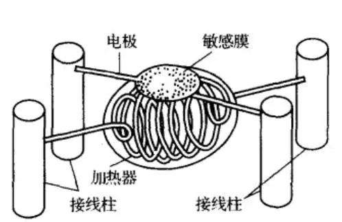
SnO2 resistive gas-sensitive devices typically use sintering processes. They are made from porous SnO2 ceramics as the substrate material, with various other substances added, and are sintered using ceramic processing techniques, embedding heating resistance wires and measurement electrodes during sintering. Additionally, thin film devices and multilayer film devices made using evaporation and sputtering techniques are also available; these devices have high sensitivity and good dynamic characteristics. There are also thick film devices and mixed film devices made using screen printing techniques, which have the advantages of high integration, easy assembly, convenience, and suitability for mass production.
The image below shows a typical structure of a resistive gas sensor, which mainly consists of SnO2 sensitive elements, heaters, electrode leads, bases, and stainless steel mesh covers. This sensor has a simple structure, is easy to use, and can detect reducing gases, flammable gases, vapors, etc.
The main characteristic parameters of resistive gas sensors are:
1. Inherent resistance R0 and working resistance Rs
The inherent resistance Ro, also known as normal resistance, indicates the resistance value of the gas sensor under normal air conditions. The working resistance Rs indicates the resistance value of the gas sensor in a certain concentration of the measured gas.
2. Sensitivity S
Usually expressed as S=Rs/R0, sometimes also represented by the ratio of the resistance values of the component in two different concentrations C1 and C2 of the detected gas: S=Rs(C2)/R0(C1).
3. Response time T1
This reflects the dynamic characteristics of the sensor, defined as the time required for the sensor’s resistance to stabilize at a certain concentration of gas after contact. It is often represented by the time taken to reach a 63% change in resistance value at that concentration.
4. Recovery time T2
Also known as desorption time. This reflects the dynamic characteristics of the sensor, defined as the time taken for the sensor’s resistance value to return to the normal air condition resistance after detaching from the detected gas.
5. Heating resistance RH and heating power PH
RH is the resistance value of the heating wire providing the working temperature for the sensor, and PH is the heating power required to maintain the normal working temperature.
Resistive gas sensors have advantages such as low cost, simple manufacturing, high sensitivity, fast response speed, long lifespan, low sensitivity to humidity, and simple circuitry. However, they must operate at high temperatures, have poor selectivity to gases, exhibit parameter dispersion, lack ideal stability, and have high power requirements. They are also prone to poisoning when detecting gases mixed with sulfides.
Non-Resistive Semi-conductor Gas Sensors
Non-resistive types are also a common category of semi-conductor gas-sensitive devices, which are easy to use, do not require a set working temperature, and are easy to integrate, leading to widespread applications. They mainly include junction type and MOSFET type.
Junction Type Gas-Sensitive Devices
Junction type gas-sensitive devices, also known as gas-sensitive diodes, work by utilizing the gas to change the rectifying characteristics of the diode. Its structure is shown in the left image below. The principle is that noble metal Pd is selective to hydrogen, forming a contact potential barrier with the semiconductor. When the diode is forward biased, electrons flowing from the semiconductor to the metal increase, thus allowing conduction. When a reverse bias is applied, the carrier changes little, which is the rectifying characteristic of Schottky diodes. In the detection atmosphere, due to the adsorption of hydrogen, the work function of the noble metal changes, weakening the contact potential barrier, leading to an increase in carriers and forward current, causing the rectifying characteristic curve of the diode to shift left. The right image below shows the characteristics curve of a Pd-TiO2 gas-sensitive diode in air with different concentrations of H2. Therefore, by measuring the forward current of the diode, the concentration of hydrogen can be detected.
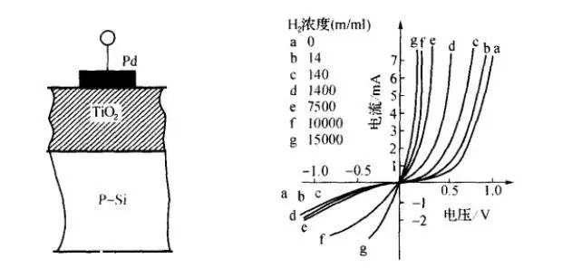
MOSFET Type Gas-Sensitive Devices
The left shift of the characteristic curve of the gas-sensitive diode can be viewed as a change in the conduction voltage of the diode, and if this characteristic occurs at the gate of a field-effect transistor, it will change the threshold voltage UT of the field-effect transistor. Utilizing this principle, MOSFET type gas-sensitive devices can be made.
Hydrogen-sensitive MOSFETs are a typical type of gas-sensitive device, made with a palladium (Pd) gate. In an atmosphere containing hydrogen, due to the catalytic action of palladium, hydrogen molecules decompose into hydrogen atoms that diffuse to the interface between palladium and silicon dioxide, ultimately leading to a change in the threshold voltage UT of the MOSFET. During use, the gate and drain are often shorted to ensure the MOSFET operates in the saturation region, where the drain current ID=β(UGS—UT)², allowing for the measurement of hydrogen concentration using this circuit.
Characteristics of Hydrogen-Sensitive MOSFETs:
1. Sensitivity
When the hydrogen concentration is low, hydrogen-sensitive MOSFETs exhibit high sensitivity; a change of 1 ppm in hydrogen concentration can yield a value of △UT up to 10 mV. However, as the hydrogen concentration increases, the sensor’s sensitivity decreases.
2. Gas Selectivity
The “gaps” between palladium atoms allow hydrogen atoms to pass through, thus the palladium gate only permits hydrogen to pass, providing good selectivity.
3. Response Time
The response time of this device is influenced by temperature and hydrogen concentration; generally, the higher the temperature and hydrogen concentration, the faster the response. At room temperature, the response time is typically several tens of seconds.
4. Stability
In practical applications, there is a characteristic of UT drifting over time. To address this, a layer of SiO2 insulating layer is grown in an HCl atmosphere, which can significantly improve the drift of UT.
Besides hydrogen, other gases cannot pass through the palladium gate. To create Pd-MOSFET gas-sensitive sensors for other gases, certain measures must be taken. For example, to create a CO-sensitive MOSFET, small holes of about 20 nm can be made on the palladium gate to allow CO gas to pass through. Additionally, since Pd-MOSFETs have high sensitivity to hydrogen but low sensitivity to CO, a protective layer of aluminum about 20 nm thick can be evaporated onto the palladium gate to block hydrogen. Palladium has a weak catalytic effect on the decomposition reaction of ammonia, so a layer of active metals such as Pt, Ir, or La can be deposited on the SiO2 insulating layer before making the palladium gate to create an ammonia-sensitive MOSFET.
Solid Electrolyte Gas Sensors
Solid electrolytes are solid materials that have ionic conductivity characteristics similar to those of electrolyte aqueous solutions. When used as gas sensors, they function as batteries. They do not require gas to dissolve in the electrolyte through a permeable membrane, thus avoiding issues such as solution evaporation and electrode consumption. Due to their high conductivity, good sensitivity, and selectivity, these sensors have been widely applied in various fields such as petrochemicals, environmental protection, mining, and food, second only in importance to metal-oxide semiconductor gas sensors.
Principle of Solid Electrolyte Oxygen Sensors
Solid electrolytes exhibit significant conductivity only at high temperatures. Zirconia (ZrO2) is a typical material for gas sensors. Pure zirconia has a monoclinic crystal structure at room temperature, which undergoes a phase transition to a polycrystalline structure at around 1000°C, accompanied by volume shrinkage and an endothermic reaction, making it an unstable structure. By doping ZrO2 with stabilizers such as calcium oxide (CaO) or yttrium oxide (Y2O3), it can be stabilized into a fluorite cubic crystal structure, with the stability degree depending on the concentration of the stabilizer. After doping ZrO2 with stabilizers, it is sintered in an atmosphere at 1800°C, where some zirconium ions are replaced by calcium ions, forming (ZrO·CaO). Since Ca2+ is a divalent cation and Zr4+ is a tetravalent cation, to maintain electrical neutrality, oxygen ions O2- vacancies are generated within the crystal, which is the reason (ZrO·CaO) can conduct oxygen ions at high temperatures. However, to truly conduct oxygen ions, there must be a difference in oxygen partial pressure (oxygen gradient) on both sides of the solid electrolyte, forming what is known as a concentration battery. The structural principle is shown in the diagram, with porous noble metal electrodes on both sides and a dense ZrO·CaO material forming a sandwich structure in the middle.
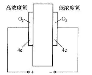
Let the oxygen partial pressures on both sides of the electrodes be PO2(1) and PO2(2), and the following reactions occur at the two electrodes:
(+) electrode: PO2(2), 2O2-→O2+4e
(-) electrode: PO1(1), O2+4e→2O2-
The electromotive force of the above reactions is expressed by the Nernst equation:

It can be seen that at a certain temperature, fixing PO2(1), the concentration of the oxygen gas to be measured at the (+) electrode can be determined using the above equation.
Fixing PO2(1) effectively forms a fixed potential electrode at the (-) electrode, known as a reference electrode, which can be a gas reference electrode such as air or other mixed gases like H2-H2O, CO-CO2 that can also form a fixed PO2(1). A coexisting phase reference electrode refers to a mixture of metal-metal oxides or low-valent metal oxides-high-valent metal oxides (solid phase), which can undergo oxidation reactions with oxygen (gas phase) to form a constant oxygen pressure, thus serving as a reference electrode.
In addition to measuring oxygen, solid electrolyte sensors made from β-Al2O3, carbonates, NASICON, etc., can also be used to measure gases such as CO, SO2, NH4, etc. In recent years, gas sensors made from antimony acid, La3F, etc., that can be used at low temperatures have also emerged, and can be used to detect cations.
Infrared Gas Sensors
Operating Principle
Molecules composed of different atoms have unique vibrational and rotational frequencies. When exposed to infrared light of the same frequency, they will undergo infrared absorption, resulting in changes in infrared light intensity. By measuring the changes in infrared intensity, the gas concentration can be determined. It should be noted that vibration and rotation are two different forms of motion, and these two forms correspond to different infrared absorption peaks. Generally, a single gas molecule will have multiple infrared absorption peaks; thus, determining the exact type of gas requires examining all the absorption peak positions in the mid-infrared region, which is the gas’s infrared absorption fingerprint. However, under known environmental conditions, a rough determination of the gas type can be made based on the position of a single infrared absorption peak. Since all substances above absolute zero (−273°C) emit infrared radiation, and infrared radiation is positively correlated with temperature, infrared gas sensors typically consist of a pair of infrared detectors to eliminate variations in infrared radiation caused by environmental temperature changes.
A complete infrared gas sensor consists of an infrared light source, optical cavity, infrared detector, and signal conditioning circuit.
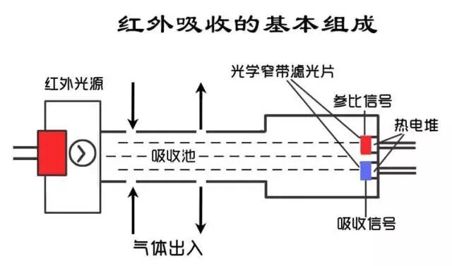
Why can’t infrared gas sensors measure gases like oxygen, hydrogen, and nitrogen, which are composed of the same atoms?
The moon and the earth, as well as the earth and the sun, are connected by gravity. The atoms within molecules are connected by chemical bonds. If both were ideal spheres without other gravitational interference, the earth’s orbit would be circular. In reality, neither of these conditions holds, so the orbit is elliptical, meaning the distance between the earth and the sun continuously changes between a short radius and a long radius, which is a vibration that takes a year. During this process, when the earth is at the short radius point and the long radius point, the gravitational force between it and the sun differs, resulting in different energy levels. Within molecules, the distances, angles, and directions between atoms change continuously due to uneven electron distribution, resulting in vibrations and rotations. Different molecules have unique vibrational and rotational frequencies, and when exposed to infrared light of the same frequency, resonance occurs, causing changes in the distances between atoms and electron distributions, which leads to changes in dipole moments, resulting in infrared absorption (the same applies to ultraviolet absorption).
The above content includes two basic conditions for infrared absorption: resonance and changes in dipole moments. Both conditions must be met to produce infrared absorption.
Why do molecules composed of the same type of atoms, such as oxygen, hydrogen, and nitrogen, not have infrared absorption peaks? The first condition is that the vibrational frequency of the gas molecule must match the frequency of the incident infrared light, and the second condition is that there must be a change in dipole moments. The first condition is easy to satisfy, while the second condition is impossible.
Molecules composed of the same atoms have their positive and negative charge centers completely overlapping, resulting in a dipole moment of zero. As a result, the electron distribution within the molecule is balanced. Given the low energy density characteristics of infrared light, its irradiation will not change this balance, nor will it ionize the molecule, meaning no energy change occurs. In contrast, for molecules composed of different atoms, such as water vapor, the electron distribution within the molecule is biased towards the oxygen end, meaning that at the microscopic level, the hydrogen end of the water molecule is positively charged, while the oxygen end is negatively charged, resulting in a non-overlapping positive and negative charge center, thus yielding a non-zero dipole moment. This is because oxygen has a stronger ability to attract electrons than hydrogen.
When infrared light with a frequency matching the vibrational and rotational frequencies of water molecules is irradiated, it causes the electron distribution within the water molecule to shift further towards the oxygen end, leading to a decrease in the average distance between hydrogen and oxygen, thus shortening the dipole moment and increasing energy. Therefore, when water molecules are irradiated with infrared light, they transition from a low energy level to a high energy level, resulting in infrared absorption. A simple way to understand this is that when infrared light encounters molecules composed of the same atoms, the interaction is akin to an ideal elastic collision, where only energy is exchanged without energy transfer. In contrast, the interaction between molecules composed of different atoms and infrared light involves energy transfer. Thus, the principle of infrared absorption cannot be used to measure molecules composed of the same atoms.
Non-Dispersive Infrared Absorption Gas Sensors
Non-dispersive: white light passing through a prism is divided into seven colors: red, orange, yellow, green, blue, indigo, and violet. This prism is a spectral system that can separate the seven colors of light. Optical systems with a spectral system are called dispersive optical systems, while those without a spectral system are called non-dispersive optical systems. Non-dispersive systems are simple, reliable, compact, and inexpensive. The white light, ultraviolet, and infrared light we usually perceive are all mixed light of different frequencies and wavelengths, while monochromatic light is light of a single frequency and wavelength. As mentioned earlier, infrared absorption occurs only when the frequency of infrared light matches the vibrational and rotational frequencies of gas molecules. Therefore, in designing gas sensors, we ideally want to use monochromatic light to irradiate the gas or obtain monochromatic light using a grating (filter) after irradiation.
Non-dispersive infrared gas sensors typically consist of a light source, optical cavity, filter (grating), detector, and signal conditioning circuit, where the filter and detector are integrated within the sensor.
Advantages of Infrared Gas Sensors:
1. All gases can be measured except those composed of the same atoms.
2. Full range.
3. The sensing process itself does not interfere with the sensing.
Disadvantages:
1. Expensive. Infrared gas sensors are essentially temperature sensors where infrared radiation causes changes in detector temperature, leading to changes in electrical performance, making the sensing process complex. The system must have the following characteristics: the light source must emit stable infrared radiation; the physical and chemical properties of the optical cavity must be stable; the filter and infrared detector must be stable. While reasonable process technology can address these issues, the high manufacturing costs lead to high prices.
2. In ordinary designs using broad-spectrum infrared light sources, filters, and detectors, the filters themselves cannot achieve ideal selective filtering, leading to interference, especially from water. The underlying reason for the selectivity issue is that many different gas molecules have the same chemical bonds, resulting in similar or even overlapping infrared absorption.
3. Dust, background radiation, and strong adsorption, as well as the detection of objects that easily transition between gas, liquid, and solid states, can all affect the detection results.
Catalytic Combustion Gas Sensors
Operating Principle
Typically consists of a high-purity platinum wire with a diameter of 15um, 20um, or 30um, wrapped in a carrier catalyst in the form of a sphere. Under certain temperature conditions, when combustible gases come into contact with the aforementioned sphere, they undergo a vigorous flameless combustion reaction with the adsorbed oxygen on its surface. The heat released from the reaction causes a temperature change in the platinum wire, which in turn causes a change in the resistance of the platinum wire. Measuring the change in resistance allows for the detection of gas concentration.
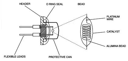
Thus, rather than saying the catalytic element is a gas sensor, it is more accurate to say it is a temperature sensor. To overcome interference from environmental temperature changes, the catalytic element is typically paired to form a complete element, where one responds to the gas while the other responds only to the environmental temperature, allowing the two elements to counteract each other and eliminate interference from environmental temperature changes.
Compared to semiconductor elements, the sensing process of catalytic elements is more complex. In the former, the chemical reaction that occurs when the gas contacts the sensor directly leads to changes in the sensor’s resistance and electrical signal. In the latter, the chemical reaction occurring on the catalytic element first results in temperature changes on the surface and inside of the carrier, and this temperature change, through heat transfer, ultimately leads to changes in the resistance of the platinum wire, completing the entire sensing process.
Existing Issues
The complexity of the sensing process increases the likelihood of issues arising.
1. For long-chain organic compounds and unsaturated hydrocarbons, incomplete reactions lead to carbon deposition, which affects the reaction process but does not significantly impact electron transport for semiconductors. However, for catalytic elements, the presence of carbon not only affects the reaction process but also significantly impacts heat transfer, resulting in reduced efficiency in transferring the heat generated by the reaction to the sensor, causing most of the heat to dissipate. Ultimately, for the same gas concentration and heat released, the sensor’s temperature only changes slightly, leading to reduced sensitivity.
2. Due to the need for heat transfer, the reaction must be completed instantaneously to ensure thermal efficiency, requiring a high reaction efficiency, which necessitates a large amount of nano-sized catalysts and nano-sized pores. These characteristics are beneficial for sensing but also make the sensor susceptible to poisoning.
3. The linearity of the catalytic element is determined by two factors: a) the temperature sensing material’s (platinum wire) resistance-temperature characteristics are linear; b) the heat released during the reaction below the lower explosive limit is linear with gas concentration. Therefore, any change in either of these two factors will lead to changes in the sensor’s linearity. In practice, the platinum wire continuously sublimates and thins, increasing its resistance; the linear relationship between the heat released and concentration only holds when the gas concentration is below the lower explosive limit.
Future Development
The future of catalytic elements mainly depends on advancements in process technology:
1. Structural improvements to address drift caused by vibrations.
2. Improvements to filtering layers to address poisoning issues.
3. Development of new materials to improve carbon deposition.
4. Ensuring the manufacturing process supports design implementation to avoid deformation.
5. MEMS integration. It should be noted that improvements in device structure, packaging, and manufacturing processes will not only enhance the overall performance of the elements but also lead to new applications. Compared to semiconductors, the challenge of MEMS integration for catalytic elements lies in achieving higher catalytic and thermal efficiency on a smaller surface area.
6. The application positioning of catalytic elements will become more precise and specialized.
7. Catalytic elements will not be eliminated.
Electrochemical Sensors
Electrochemistry is the study of the relationship between electrical and chemical behaviors. The most important application of this discipline is the efficient conversion of electrical energy and chemical energy, as well as high power density storage technology. We know that sensors are essentially energy conversion devices; for example, pressure sensors convert mechanical energy into electrical energy. Therefore, it is easy to understand that electrochemical gas sensors are a type of battery, known as gas fuel cells.
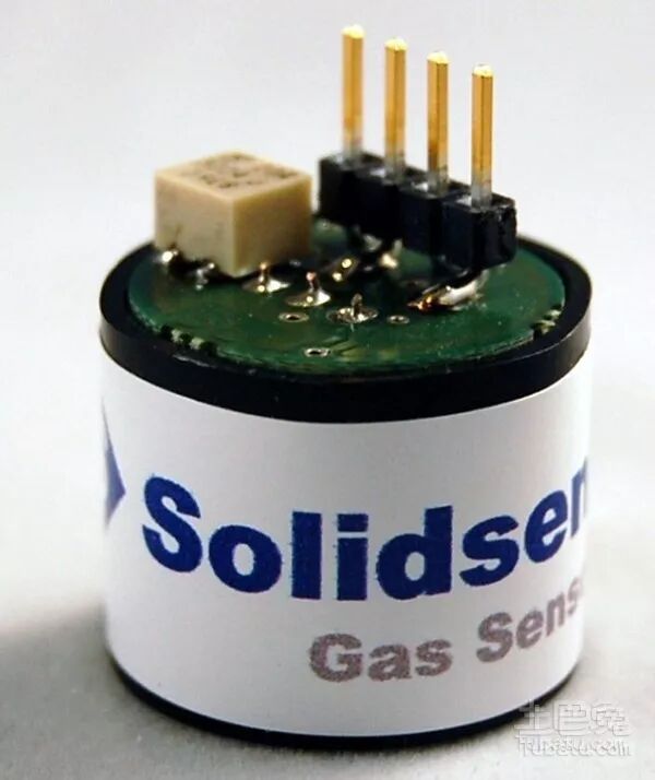
The most common battery consists of a collection of conductive chemical substances enclosed within two electrodes made of different materials, connected by wires to generate electricity. Taking lead-acid batteries as an example, sulfuric acid solution serves as the conductive chemical substance. When lead is placed in it, electricity is generated at the interface where lead contacts sulfuric acid, and when lead oxide is added, electricity is also generated at that interface. The two interfaces have different electric charges, resulting in voltage, and when connected by wires, electrons flow from lead to lead oxide, converting lead into lead oxide and lead oxide into lead sulfide. The electric charge is related to the chemical quantity and reaction process.
The key concepts here are: first, inserting a conductor into a conductive chemical substance generates a potential at the interface, and inserting different conductors into the same substance generates different potentials. Second, connecting different potentials leads to reactions at the interface. Third, the conductive circuit consists of the battery and external wires. The conduction process is completed by the movement of electrons and ions.
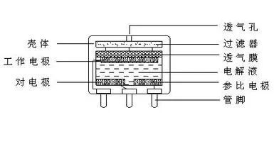
The electrochemical CO gas sensor is a chemical battery, specifically a CO fuel cell. In this case, CO serves as the electron-donating electrode (working electrode), while oxygen serves as the electron-accepting electrode, with sulfuric acid solution acting as the electrolyte. The main difference from lead-acid batteries lies in the different electrode materials; the electrodes in electrochemical gas sensors (CO) are gases, while those in lead-acid batteries are solids. The electrodes in electrochemical gas sensors are referred to as gas electrodes. In the electrochemical CO gas sensor, the working electrode CO serves as the electron-donating electrode, and the process of electron release, collection, and conduction cannot occur without contact between CO and sulfuric acid solution. This process requires conditions that lower the difficulty of CO providing electrons under electrocatalytic conditions. In practice, this condition is provided by a porous platinum electrode (or other electrocatalytic conductive electrodes). Similarly, the oxygen electrode as the counter electrode also requires assistance from a porous platinum electrode to obtain electrons. The platinum electrode essentially serves as a reaction platform. Although the principle of electrochemical sensors is simple, achieving reliable and accurate sensing is challenging: first, the platinum electrode must have a stable porous structure with a sufficient number of pores, allowing sulfuric acid solution to enter the pores, and CO (or oxygen) to also enter the pores, completing the electron donation at the three-phase interface where gas (CO)-solid (Pt)-liquid (sulfuric acid solution) come into contact. Therefore, maintaining the stability of the three-phase interface under long-term immersion in sulfuric acid, the impact of electrochemical reactions, and electrophoretic driving is crucial for reliable and accurate sensing. Second, the sulfuric acid solution must be stable, non-volatile, non-hygroscopic, and leak-proof. Any change in the quality of the sulfuric acid solution will lead to changes in internal pressure, subsequently affecting the three-phase interface. Third, the contact stress between the electrode and sulfuric acid solution, determined by the physical properties of the packaging and materials, must remain stable and unchanged.
Currently, the main issues with electrochemical sensors stem from the factors mentioned above. One of the core technologies and processes for electrochemical sensors is how to construct a physically stable and reliable electrode structure with pores, which is closely related to sensitivity, response recovery, lifespan, and temperature characteristics. Secondly, packaging is also critical. Issues with electrochemical sensors include dehydration and deactivation under dry conditions, water absorption and leakage under high humidity conditions, poisoning and deactivation due to long-term contact with the measured gas, and deactivation due to the disintegration of the electrode pore structure. Performance issues manifest as leakage, short lifespan (compared to other principles), and large size. Manufacturing issues are reflected in complex design and processes, leading to high manufacturing costs.
The future of electrochemical sensors: a clear direction is to achieve room-temperature solidification of the electrolyte and subsequently realize MEMS integration. Solidification and MEMS integration of electrochemical sensors can not only overcome most issues, including manufacturing challenges, but also stimulate new applications, bringing new growth to enterprises. At this point, electrochemical sensors will be highly integrated, easy to integrate, and compact electronic systems. However, this outcome still cannot overcome performance changes in sensors caused by long-term contact with high concentrations of the measured gas.
PID – Photoionization Detectors
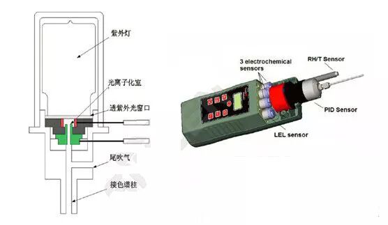
PID consists of a UV light source and a gas chamber. The principle of UV light emission is similar to that of fluorescent lamps, but at a higher frequency and energy. When the measured gas enters the gas chamber, the UV light emitted by the UV lamp ionizes it, generating a charge flow. The gas concentration is directly proportional to the magnitude of the charge flow, and measuring the charge flow allows for the determination of gas concentration.
Special gases: physical forms vary, and chemical processes and reaction products are complex and diverse. This includes inorganic gases such as ammonia and organic gases such as toluene.
The various gas sensors introduced earlier face significant challenges in detecting complex gases. For example, in detecting organic vapors, the infrared absorption principle faces insurmountable difficulties: a) due to the large molecular weight of organic vapors, the characteristic absorption wavelengths are longer, resulting in low sensitivity due to minimal energy changes after infrared absorption. b) Long-chain organic vapors are prone to adsorption, adhering to the detector and disrupting light transmission. c) It is impossible to achieve total VOC detection. If the infrared system aims to achieve total evaluation, it requires filters, detectors, and full-spectrum infrared light sources that respond across the entire spectrum. Such requirements are not only difficult to achieve but even if accomplished, inorganic gases and water will naturally interfere across the full spectrum. In this context, PID is a better choice for VOC detection in industrial settings.
Compared to other sensors, the most significant feature of PID is its sensitivity to only a few inorganic gases, such as ammonia and phosphine. This is because most inorganic gases have high ionization energies (greater than 11.7 eV). Currently, the highest UV radiation energy from PID lamps is only 11.7 eV. Therefore, in petrochemical parks, the response of PID can be considered as the response to VOCs.
Working Principle of PID
1. High-purity rare gases such as argon or krypton are filled into a vacuum glass chamber.
2. The glass chamber is sealed with a magnesium fluoride single crystal UV transparent window, which allows UV light to pass through.
3. Electrodes are placed on the outer wall of the glass chamber.
4. An electrode and electric field are applied at the magnesium fluoride window, forming the gas chamber for the measured gas, creating a complete UV lamp capable of ionizing VOCs. During operation, a high-frequency electric field is applied outside the glass chamber, ionizing the rare gas within the UV lamp to produce electrons and ions. When electrons and ions recombine, they emit energy in the form of UV light. The UV light passes through the magnesium fluoride window to the gas chamber, where the measured gas is ionized by the UV light, generating electrons and ions. Under the influence of the electric field, a current is produced, which can be measured.
PID Stability Requirements:
1. PID must emit sufficient energy to ionize the measured gas;
2. The high-frequency electric field generating the UV light must be stable.
3. The glass chamber must be free of impurity gases, as impurities can lead to additional ionization, affecting UV light emission efficiency.
4. The UV spectrum must be stable and uniform.
5. The transmission of UV light to the gas chamber must be stable and uniform, without interaction with the metal electrode materials constituting the gas chamber, which could lead to heavy metal deposition. Heavy metals deposited on the UV radiation window will block UV light from reaching the gas chamber.
This requires that the light-emitting substance filled in the UV lamp must be a gas to ensure uniform emission and transmission. The chamber must be free of impurity gases to prevent additional ionization. These requirements limit the choice of light-emitting gases to rare gases. The choice of window materials must also be UV transparent and possess stable physical and chemical properties; in fact, the selection of UV window materials is extremely limited. These limiting conditions ultimately determine the limitations of PID applications.
Why can’t current PID measure propane, ethane, methane, and most inorganic substances?
The essence of PID is to measure the charge flow after ionizing the measured substance, which requires energy for ionization. Currently, the most common UV radiation energy from PID lamps is 8.3 eV, 9.8 eV, and 10.6 eV. Ionizing methane requires 12.6 eV, ethane requires 11.56 eV, propane requires 10.95 eV, and carbon dioxide requires 13 eV. In fact, there is a strong desire to develop PID lamps with higher energy outputs, but the limiting conditions are that the types of rare gases are extremely limited, and the UV wavelength (energy) is determined by the electronic energy levels of the rare gases themselves, which cannot be altered by humans. Another limiting condition is the window material’s lattice constant, which determines the wavelengths of UV light that can pass through; the selection of suitable window materials is also extremely limited. Although efforts have been made to develop light sources with 11.7 eV, the only suitable window material is lithium fluoride (LiF), which is highly hygroscopic, leading to a lifespan of only two months for 11.7 eV PID lamps. Thus, due to the limitations of output energy, current PID lamps still cannot detect substances with higher ionization energies like methane.
Why does PID lack selectivity?
If the UV radiation energy of the selected PID is 10.6 eV, it means that all gas molecules in the environment with ionization energies less than 10.6 eV will be ionized. The charge flow we measure is the sum of the charge flows from all ionized gases, rather than from a specific gas. The lack of selectivity in PID is thus determined.
During operation, the substances ionized in the gas chamber will recombine, and long-chain molecules, dust, etc., will deposit on the window surface. Additionally, the ion flow generated during sensor operation will bombard the gas chamber electrodes, causing heavy metals to deposit on the window surface, which will obviously affect UV light transmission, leading to zero drift and reduced sensitivity, thus impacting detection results. In fact, besides the preparation technology of PID lamps and gas chamber design, the cleaning technology for the UV transmission window is also one of the core technologies.
Future of PID
1. PID will always exist as an ideal non-radioactive ion source;
2. Improve the vacuum level before filling the PID lamp and the purity of the filling gas to enhance light emission efficiency and stability;
3. Develop new window materials and processing precision to improve light transmission, emitted light uniformity, packaging quality, stability, and lifespan;
4. Prevent dispersion from causing heavy metal deposition on the window to extend lifespan;
5. Develop cleaning technologies for the window to prevent deposition of large organic molecules and small particles;
6. Develop PID lamps with higher output energy and longer lifespans;
7. Smaller size.
Development Directions for Gas Sensors
The research on gas sensors is broad and complex, belonging to interdisciplinary research. To effectively improve the performance indicators of sensors, collaboration among researchers from multiple disciplines and fields is essential. The development of gas-sensitive materials and the rational design of sensor structures based on different principles have always been a focus of researchers. Future development of gas sensors will also revolve around these two aspects. Specifically, this will manifest as:
Further development of gas-sensitive materials, on one hand, involves searching for new additives to further enhance the performance of already developed gas-sensitive materials; on the other hand, it fully utilizes new material preparation technologies such as nanomaterials and thin films to find superior gas-sensitive materials.
The development and design of new gas sensors will be based on the different effects that gases may have on gas-sensitive materials, leading to the design of new types of gas sensors. In recent years, the successful development of new types of sensors such as surface acoustic wave gas sensors, optical gas sensors, and quartz crystal gas sensors has further broadened the designers’ horizons. Currently, biomimetic gas sensors are also under research.
Further research into the sensing mechanisms of gas sensors is necessary, as new gas-sensitive materials and new types of sensors continue to emerge. A deep theoretical study of their sensing mechanisms is essential. Only by clarifying the mechanisms can future work avoid unnecessary detours.
The rapid development of intelligent production and life imposes higher demands on gas sensors. The intelligence of gas sensors is an inevitable path for their development. Intelligent gas sensors will be developed based on the comprehensive application of technologies from micro-mechanics, micro-electronics, computer technology, signal processing technology, circuits and systems, sensing technology, neural network technology, and fuzzy theory.
The rapid development of biomimetic gas sensors: the nose of a police dog is an ideal gas-sensitive sensor with both high sensitivity and selectivity. Combining biomimicry with sensor technology to study an “electronic nose” similar to a dog’s nose will be one of the important directions for the development of gas sensors.