As an experienced electrical engineer, I want to share some core insights on PLC control cabinet design. Whether you are a newcomer to the field or a seasoned professional looking to refine your skills, this content is worth saving for future reference—it might come in handy during your next wiring project! 🔧 First, engrave the “Wiring Rules” in your mind
1. Wire according to the diagram: This is the baseline and the red line!
We electrical engineers often say, “The drawing is the soul,” and this is absolutely true. Before wiring, never rely on “common sense” or “old experience”; you must read the drawing thoroughly from start to finish. For instance, when I receive a new drawing, I first circle the key points such as input and output points and the power direction. If I encounter any unclear symbols or circuit contradictions, I immediately consult the designer—don’t hesitate; it’s better to ask than to make mistakes and have to redo the work. Only after all questions are resolved should you start wiring; this is the most efficient approach.
2. Wiring sequence: Don’t rush; following the correct process saves trouble
Honestly, I’ve seen too many professionals trying to cut corners: just crimping the wire ends, tightening the terminals, and closing the cover. But when troubleshooting equipment issues later, they are left with a tangled mess of wires… The correct approach is to wiring in the order of “main circuit first, then control circuit, and input before output”, and after completing each group of wires, make clear markings, such as using wire number tubes to indicate “where it comes from and where it goes”. This way, during later inspections or maintenance, it will be clear at a glance, saving time and effort.
3. Wiring techniques: Use the right tools for better results 💡
It’s normal to encounter small challenges while wiring, so here are some practical experiences for common issues:
Q: In a PLC cabinet, there are many terminal blocks and terminals, and I often struggle with wire ends, either they are loose or have burrs. Should I strip the wire and insert it directly, use pins, or solder?A: For single-core wires, just strip and crimp them into the terminal; it’s simple and reliable. For multi-core wires, you must use cold-pressed terminals (make sure to choose the right specifications); never cut corners by soldering—soldering makes the wire ends hard, which can lead to looseness and potential oxidation issues over time.
Q: When there are many PLC expansion modules, how should the common and power terminals be connected? Should they be directly paralleled between modules or short-connected through terminal blocks?A: From a maintenance perspective, I strongly recommend short-connecting at the terminal block before distributing to each module! Just like how we distribute electricity at home, the main switch goes to the distribution box, and then it’s distributed to each room, making it clear where the problem lies. Remember to label clearly with wire number tubes or on the terminals, such as “to module 1” and “to module 2”; don’t be lazy. Additionally, choose terminal blocks with fuses or disconnectable types; in case of a short circuit, you can just pull the fuse for troubleshooting, which is much easier than disconnecting wires one by one.
🔌 PLC Internal and External Circuits: Understand these 3 points for a solid foundation
1. External circuit wiring: Transition from “hard wiring” to “soft control”
First, let’s look at traditional electrical control: Figure 1 shows the contactor control circuit for direct-on-line starting of a motor. When we press the SB1 start button, the current flows through the KM coil, FR thermal relay, and SB2 stop button, forming a circuit with these “hard components”. The KM engages, and the motor starts; pressing SB2 breaks the circuit, and the motor stops—doesn’t it resemble the logic of turning a light on and off at home?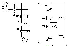 ▲Figure 1 Direct-on-line starting electrical control circuit
Now let’s look at PLC control (Figure 2): the main circuit still uses the same motor and contactor, but the control logic has changed—SB1, SB2, and FR are now connected to the PLC’s input ports, while KM coils and indicator lights are connected to the PLC’s output ports. The logic that was originally connected by wires is now implemented through the program in the PLC, making it much more flexible!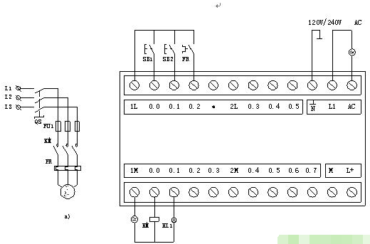 ▲Figure 2 Direct-on-line starting PLC control wiring diagram
2. Internal I/O Image Area: The PLC’s “Memo” 📝
Inside the PLC, there is a dedicated “memory area” called the I/O image area, similar to a notebook we use at work: the status of input signals (such as whether a button is pressed) is stored in the “input image register”, and the results after processing are stored in the “output image register”.
For example: When SB1 is pressed, the PLC records the status “SB1 is ON” in the I0.0 bit of the input image area (just like writing “SB1: ON” in a notebook); during program execution, it doesn’t directly check if SB1 is actually pressed, but rather checks this “notebook”—this way, the program runs faster, and external interference does not affect it, making it super reliable!
3. Internal Equivalent Circuit: Understanding the Secret of “Soft Relays”
Looking at the internal equivalent circuit of the PLC in Figure 3, let’s take SB1 as an example: it is connected to the PLC’s I0.0 interface, just like connecting a switch to the “soft relay I0.0” inside the PLC. When SB1 is ON, this “soft relay” is triggered to the “1” state, and the I0.0 contact status used in the program is the same as SB1 (if SB1 is ON, the contact is ON).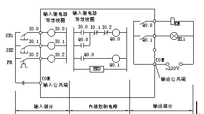 ▲Figure 3 PLC Internal Equivalent Circuit
However, the I0.1 connected to SB2 is different: the program will “reverse” the status of I0.1—when SB2 is closed, I0.1 is “1”, but the I0.1 contact in the program is actually open (due to the normally closed contact characteristic). As for the output ports Q0.0 and Q0.1, they are the “physical normally open contacts” in the PLC; once closed, the external KM coil and indicator light are powered and operational, which is super intuitive!
🛠️ Breakdown of the 3 Main Components of a PLC Control System
Using a PLC to control motor starting, the main circuit remains unchanged, but the control core is replaced by the PLC. It mainly consists of 3 parts, which we will discuss one by one:
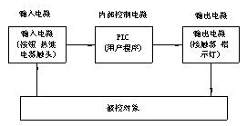 ▲Figure 4 Basic Structure Diagram of PLC Control System
1. Input Circuit: The Signal “Receiver”
The input circuit acts like a package receiving station, where signals from external devices like SB1, SB2, and FR are sent to the PLC’s “input relays” through the input ports. The key point is that these “input relays” can provide countless normally open and normally closed contacts for the program to use, unlike traditional contactor contacts which are limited in number—it’s like “unlimited refills”!
2. Output Circuit: The Signal “Transmitter”
The output circuit is the “executor”: after the PLC calculates the results, the internal “output relays” will close the corresponding contacts, driving the external KM coil and indicator light. For example, when Q0.0 closes, the KM coil is powered, and the motor starts—here, it’s important to note that the power for driving the load is provided externally, and the PLC’s COM port is the common terminal, so don’t connect it incorrectly!
3. Internal Control Circuit: The Core “Brain”
This part is implemented by the user program we write, like giving the PLC an “operation manual”. The program will calculate results based on the status of input signals (for example, whether SB1 is pressed) according to the set logic (for example, “press SB1 to start the motor”), and then control the devices through the output circuit. The best part is that modifying the program doesn’t require changing the wiring! For instance, if you want to add a “delay stop” function, you can just add a few lines of code in the program, eliminating the hassle of rewiring in traditional control cabinets!
📊 Ladder Diagram: How to Read the “Circuit Diagram” of PLC?The ladder diagram is the “language” we use to write PLC programs; it looks like a traditional electrical diagram, but there are significant differences. First, let’s look at the common symbols in Figure 5: coils, normally open contacts, and normally closed contacts are all here!Image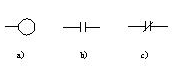 ▲Figure 5 Common Equivalent Control Element Symbols in Ladder Diagramsa) Coil b) Normally Open Contact c) Normally Closed Contact
Figure 6 shows the PLC ladder diagram for direct-on-line starting of a motor; doesn’t it look somewhat similar to the electrical diagram in Figure 1? However, it has 4 key differences from the traditional electrical diagram that you must remember: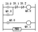 ▲Figure 6 Ladder Diagram for Direct-on-line Starting Control
1. The essence of components is different
In ladder diagrams, “coils and contacts” are not physical parts but rather “bits” in memory— for example, the I0.0 contact is essentially a storage bit in the input image area, where data “1” represents “ON” and “0” represents “OFF”.
2. ON/OFF states are different
Traditional contactor contacts rely on physical contact to switch ON/OFF, while the contacts in ladder diagrams switch based on stored bit data: storing “1” means ON, and storing “0” means OFF, with no physical wear, making them super durable!
3. Switching speeds are different
Contactor contacts have a delay in switching (for example, it takes 0.1 seconds to switch from OFF to ON), while switching contacts in ladder diagrams is instantaneous by just changing data, with no delay!
4. The number of contacts is different
Traditional contactor contacts are limited in number; once used, they are gone. However, in ladder diagrams, as long as the PLC memory is sufficient, you can duplicate as many contacts as you want (for example, the normally open contact of I0.0 can be used 10 times or 100 times in the program without issue). However, note that coils can generally only be used once; reusing the same address for a coil can lead to problems!
Finally, here’s a little tip: when drawing ladder diagrams, start from the left bus, place contacts on the left, coils on the right, with parallel components on the left and series components in the middle, making it visually clear!
💬 In Conclusion
Designing a PLC control cabinet may seem complex, but by mastering the points of “wiring according to the diagram, following standardized processes, and using techniques wisely”, and understanding the principles of internal and external circuits and ladder diagrams, it’s actually not that difficult to get started. I hope today’s content helps my fellow electrical engineers; if you have any other questions, feel free to discuss in the comments! Remember to save this for your next wiring project—it will definitely come in handy!
Previous Recommendations
Attention electricians and electronics enthusiasts! Here are 50 super practical classic circuit diagrams that are essential for design—make sure to save them!
From 6k to 300k! 8 career paths in automation, including salary tables and job analyses (this is how industry insiders choose).
Illustrated examples of complete electrical cabinet installations worth saving!
Master complex switch cabinets in three minutes—easy enough for beginners!
Little tricks used by senior engineers: HMI multiplexing variables, easy for beginners to grasp!
Get it for free! Essential manual for electricians and popular simulation tools to help you easily master circuit diagrams, improving both theory and practice!
Embedded vs. PLC programming: which one is more suitable for you? This article explains it clearly.
Industrial control automation-related positions and matching skills—see which level you belong to.
Practical sharing: Three modes of controlling a material handling cart using FX3U.
Mitsubishi PLC on-site conveyor control case, a step-by-step guide to understanding!
 Share
Share Save
Save View
View LikeFollow for more updates