1. STM32 and Selection
1.1 STM32 vs 51 Microcontroller
Both STM32 and 51 are types of small computer chips that allow us to write code and store it within. For example, we can control a pin to switch between 5V and 0V, connecting an LED to this pin to achieve a blinking effect. This operation makes both types of chips suitable for various electronic control projects.
| Core Architecture | Memory and Power Consumption | Development Tools | |
| 51 | Uses an 8-bit CPU with a simple instruction set, easy to learn and use. Internal resources include CPU, data memory (RAM), program memory (ROM), I/O ports, timers/counters, etc. | Typically has a smaller storage capacity, e.g., AT89C51 has 4KB ROM and 128B RAM. The design is relatively traditional, with higher power consumption. | The common programming languages are assembly language and C language, with relatively simple development tools like Keil uVision IDE. |
| STM32 | Based on ARM Cortex-M series cores, such as Cortex-M0, M3, M4, etc., offering higher processing power and speed. It integrates more advanced functional modules, such as various communication interfaces (USART, SPI, I2C, etc.), ADC, DAC, DMA, etc. | Provides larger storage space, e.g., STM32F103 series has up to 1MB Flash and 96KB SRAM. It adopts advanced low-power technology, suitable for battery-powered devices. | Supports multiple programming languages, including C, C++, and provides rich development tools and libraries, like STM32CubeMX and HAL library. |
In summary, STM32 is suitable for complex embedded applications due to its high performance, rich peripheral interfaces, and low power characteristics; while the 51 microcontroller is widely used in simple control applications due to its ease of use and low cost. The choice of microcontroller should be based on specific application needs and cost budget.
1.3 Domestic STM32 Candidates and Comparisons
STMicroelectronics’ STM32 microcontroller has been a leader in the embedded systems field, selling over 10 billion units over the decades. Its wide application and stable performance have won the favor of engineers worldwide. However, due to supply chain issues, price fluctuations, and changes in the international trade environment, finding suitable domestic alternatives has become a focus for many enterprises. Below is a detailed analysis of domestic alternatives to STM32:
| Compatibility and Performance Features | Potential Issues | |
| Beijing Zhaoyi Innovation – GD32 Series | GD32 series uses Cortex-M3 core, claiming full compatibility with STM32 of the same model. With over 200 million units shipped and more than 10,000 users, its extensive application coverage ranks among the top in the market. | Despite high compatibility, code adjustments may be needed in some deep applications. |
| Shanghai Lingdong Microelectronics – MM32 Series | Based on ARM Cortex-M0 and Cortex-M3 cores, products include the MM32F series for general high-performance markets, the MM32L series for ultra-low power and secure applications, and the MM32W series with various wireless connectivity features. Same pinouts and models as ST, low replacement cost. | Although compatibility is good, further optimization may be required in specific application scenarios. |
| Huada Semiconductor – HC32 Series | Based on ARM Cortex-M0+ and Cortex-M4 cores, products include HC32L series for ultra-low power applications and HC32M series for motor application markets, with high cost-performance HC32F series for general markets. Pin compatibility with ST’s same model products allows direct replacement. | In high-performance and complex applications, more technical support may be needed. |
| China Science and Technology Microelectronics (CETC) | CETC’s 32-bit MCU products can replace STM32’s F103, F030, F031, and F051 series in bulk. Hardware pins are P2P compatible with STM32, and software uses register-level compatibility design. | While compatibility is high, longer verification time may be needed for large-scale applications. |
| Artery Technology | Artery’s AT32F403A/F407/F413/F415/F421 series can replace multiple STM32 series in bulk, with hardware pins P2P compatible with STM32 and high software compatibility. | Due to significantly improved performance in cores, SRAM, and peripherals compared to STM32, some adjustments to existing systems may be needed. |
| CMSemicon | CMSemicon’s high-performance, low-power, highly integrated MCUs can replace STM32F030/031 series, STM32G030/031 series, and STM32L031/051 series in bulk. |
Performance testing and optimization may be required in specific application scenarios. |
| Hangshun | Has mass-produced MCU products based on ARM Cortex-M0 and Cortex-M3 cores, including HK32F103 family for general high-performance markets, HK32F030/031/03X family, etc. | More technical support may be needed in ultra-low power applications. |
| Geehy Semiconductor | General MCU APM32 series is designed based on ARM Cortex M3 series CPU, featuring self-designed 32-bit CPU products. | Although compatibility is good, more debugging work may be needed in complex systems. |
| Chipsea Technology | Shenzhen Chipsea Technology started with MCU for electronic scales, and has good Cortex-M0 MCUs that can serve as replacements for STM32. | Further validation may be needed in high-performance applications. |
| Nation Technology | Nation Technology, formerly ZTE Integrated Circuit Design Center, N32G/N32L series products use industry-leading process technology, with 32-bit ARM Cortex-M series core, CPU performance up to 180 DMIPS. | Performance optimization may be needed in certain special applications. |
1.4 Qinheng Microelectronics and Selection
Nanjing Qinheng Microelectronics Co., Ltd. focuses on connection technology and microprocessor core research, and is an integrated circuit design enterprise that builds integrated chips based on self-developed professional interface IP and microprocessor core IP.
WCH is known in the industry for providing cost-effective microcontrollers. These products are favored by many engineers and students due to their simple architecture, low cost, and extensive application support.
WCH has launched multiple MCU chips, and the model selected for this course is CH32F103C8T6. The main reason for choosing this microcontroller is that it has rich online learning resources, making it easier for students to access more auxiliary materials to deepen their learning.
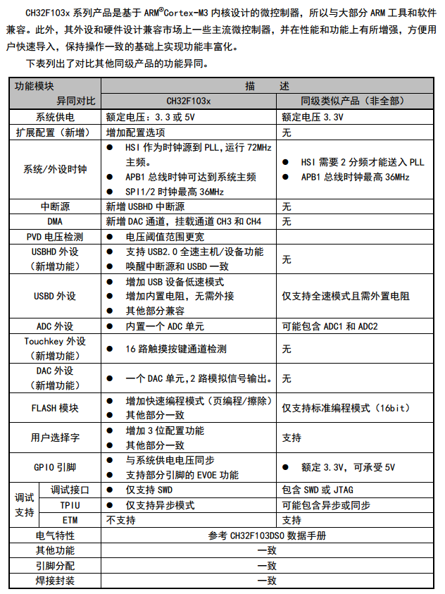
Comparison of CH32F103C8T6 with Other Similar ICs:
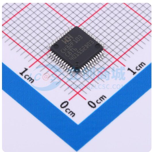
CH32F103C8T6 is in LQFP-48(7×7) package:
2.1 Core Board and Expansion Board
In embedded system design, separating the core board from the expansion board has many practical advantages. The core board typically integrates the processor, memory, and necessary interfaces, while the expansion board provides additional interfaces and functions, such as extra I/O ports, sensor interfaces, communication modules, etc.
This modular design makes the system more flexible and scalable. Developers can select the appropriate core board based on project requirements and expand or customize functionality by replacing or adding different expansion boards without redesigning the entire system. This not only shortens the product development cycle but also reduces development costs.
Furthermore, this design facilitates maintenance and upgrades. When core technologies (such as processors) need to be upgraded or replaced, only the core board needs to be replaced without affecting the expansion board, and vice versa. This allows products to adapt to rapidly changing technological environments, extending the product’s market lifecycle.
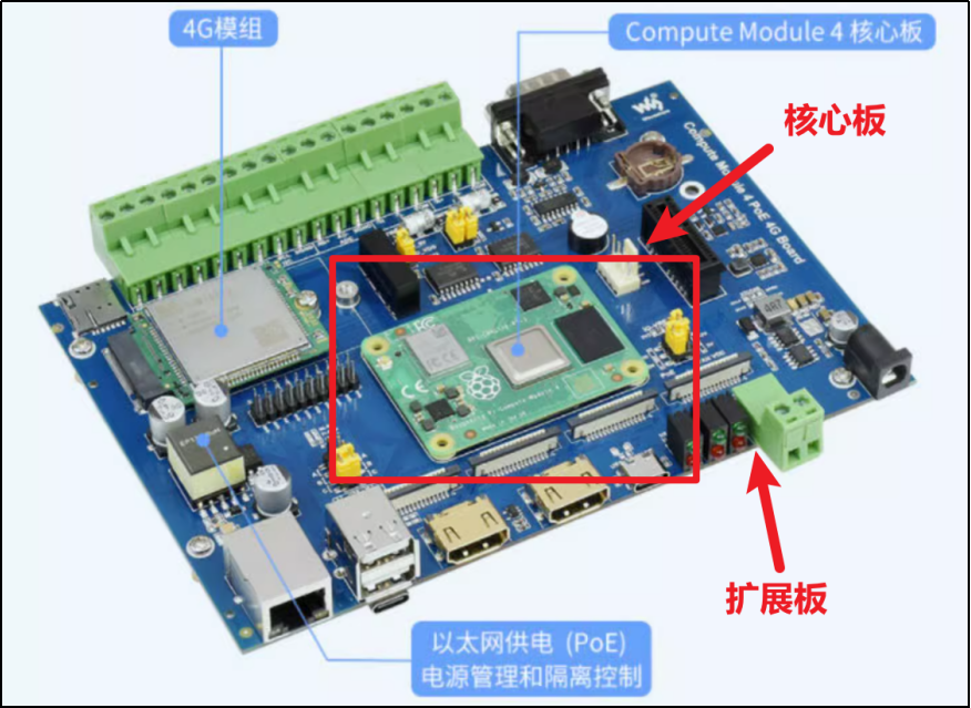
Below is the core board of Raspberry Pi CM4, which integrates the necessary master control chip, memory, and other components on the front:
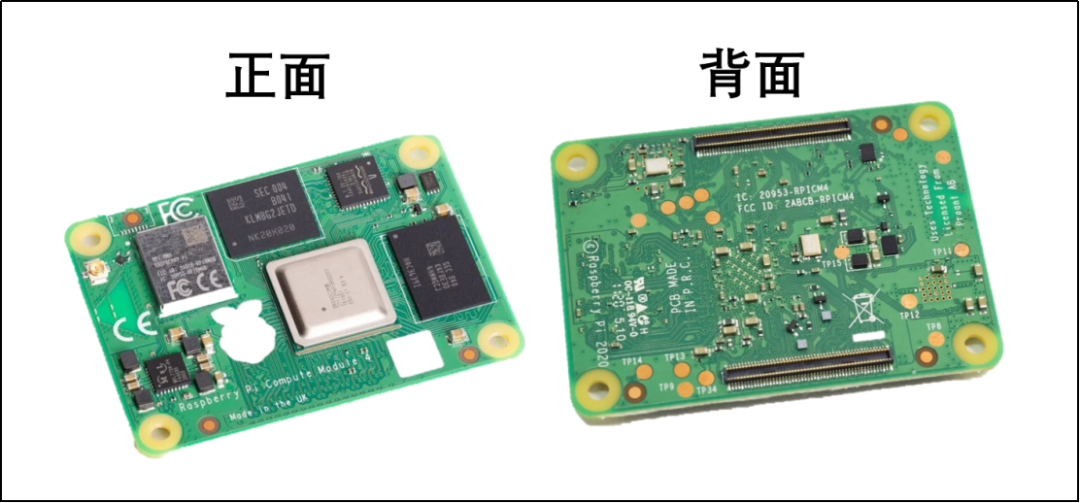
You can use the slots behind the CM4 to install the core board on different expansion boards. Different expansion boards are suitable for different R&D directions:

Once installed, as shown in the figure, embedded engineers can more conveniently and efficiently conduct code debugging and product development. This setup optimizes the development process and improves work efficiency.
2.2 Core Board Function Planning
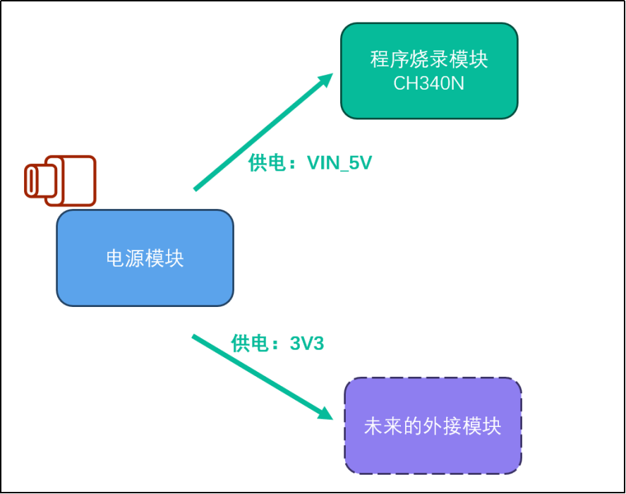
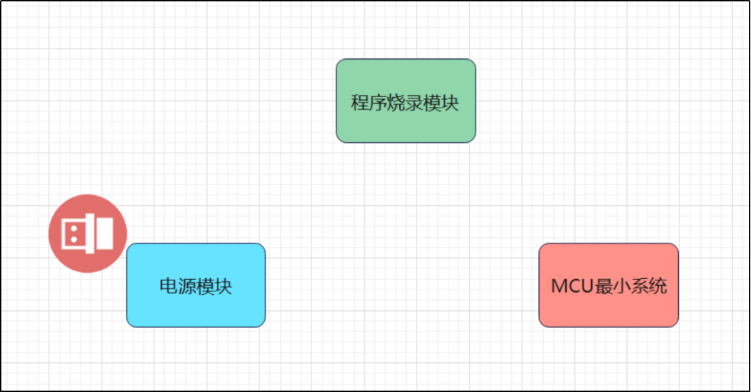
The core board only contains the circuits for three modules.
2.2.1 Power Supply Module
The power supply module receives power from an external source through a Type C interface and has the following main functions:
(1) Short Circuit Protection: When a short circuit occurs in the subsequent circuit, the power supply module will immediately stop supplying power to prevent more serious electrical damage.
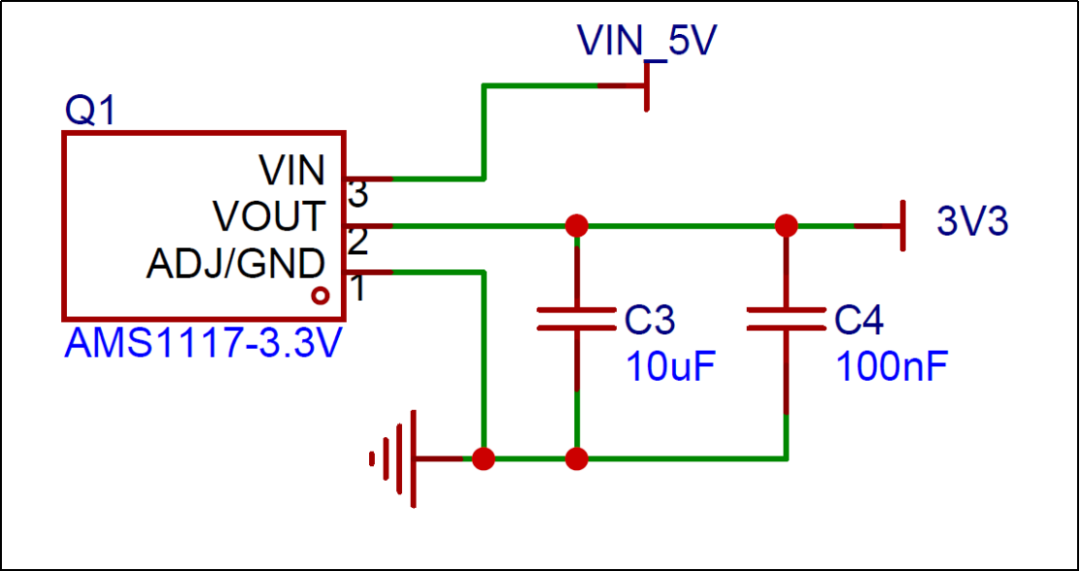
(2) Provide 3.3V Power:This module converts the 5V voltage to 3.3V, providing developers with additional voltage choices to meet different electrical requirements.
(3) Power Supply for All Components on the Core Board and Future Expansion Boards:
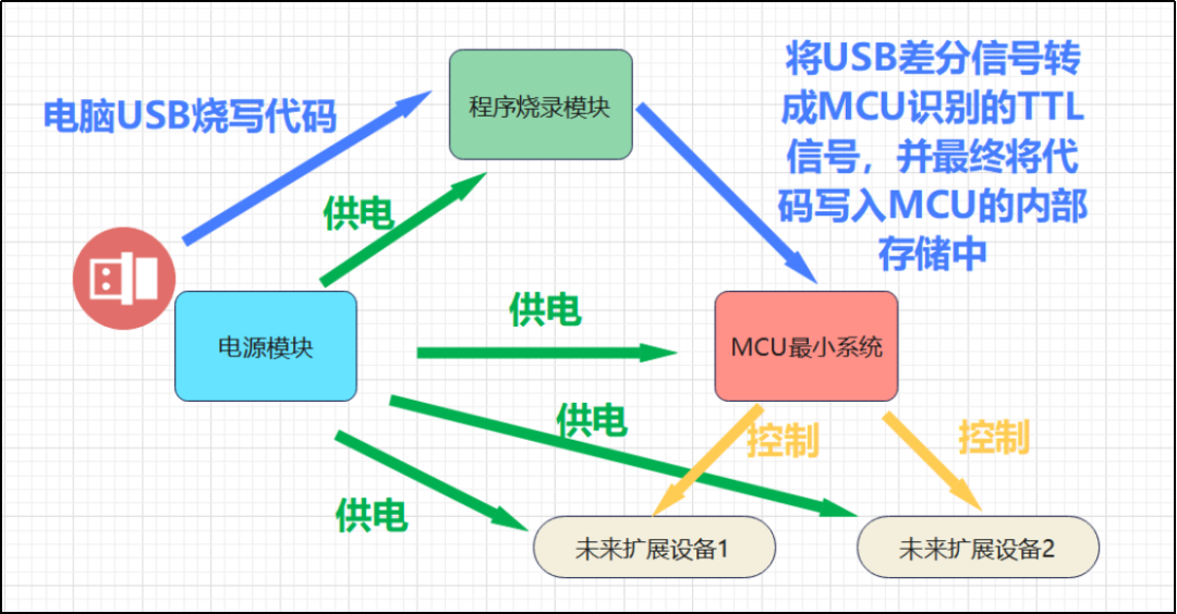
In our current design scheme, the power supply module is responsible for powering all components on the core board. Furthermore, once expansion boards are connected, these boards will also directly receive the necessary power through the power module on the core board. This design ensures centralized management and supply of power, making the system’s power distribution more efficient and unified.
2.2.2 Minimum MCU System
The minimum MCU system can be seen as the “survival mode” of the microcontroller (MCU). This design only includes the circuits necessary for the MCU to reach the most basic operational state, without involving control of external devices. Just like keeping a person alive, we only need to ensure that their brain and circulatory system are functioning normally. When this “person” needs to perform more functions, such as observing or speaking, we can consider adding “eyes” or a “mouth”. In short, the minimum MCU system is the core circuit that maintains the microcontroller’s basic “vital signs” until further functionality needs to be expanded. This design allows us to develop and test at a lower cost in the initial phase, gradually increasing functionality to meet more complex application requirements.
2.2.3 Programming Module
The programming module can communicate with a computer through a Type C interface, allowing the computer to send the code to be executed to the programming module via specific software. The programming module then converts the USB signal into a signal that the MCU can understand and writes it into the MCU‘s memory. This way, the MCU can ultimately execute the code we set.
2.2.4 Module Relationships
Finally, the cooperation relationship between our three modules is as follows:
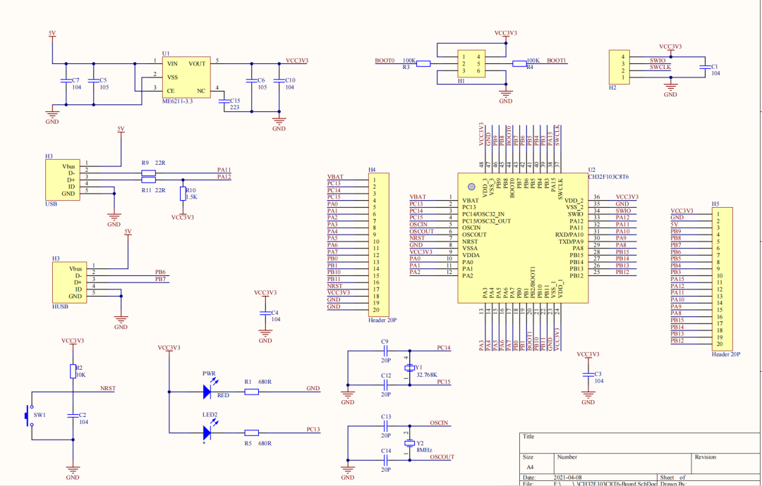
3. Final Schematic
4. Power Supply Section Schematic – Type C Connection
4.1 Component Selection
4.1.1 Self-Restoring Fuse

4.1.2 100nf Capacitor

4.1.3 16P Type C Female Interface

4.2 Schematic
6.3 Understanding LDO
6.3.1 What is LDO
LDO (Low Dropout Regulator) is a device that stabilizes the output of a specified voltage. For example, if we choose a fixed output of 3.3V, it can stabilize the output regardless of whether the input voltage is 5V, 6V, or 8V (though with minor fluctuations).LDO‘s key function is to provide stable voltage to the circuit, noting that the input voltage must always be higher than its output voltage, and it does not have boost capabilities.
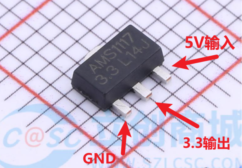
For beginners, LDO is particularly useful in the following two situations:
(1) When powered by batteries:
Battery voltage gradually decreases during discharge. For example, a fully charged lithium battery can have a voltage of 4.2V, while when fully discharged, it may drop to 3V. In this case, using LDO ensures that the circuit receives constant voltage supply.
(2) When powered by USB, but need to use 3.3V to drive circuits:
The standard power supply voltage for USB is 5V. With advancements in chip manufacturing technology, many modern IC chips require voltages of 3V or lower. While many ICs support a wide voltage range (like 2V to 6V), some ICs can only operate at specific voltages. In this case, an LDO can convert the 5V input to a stable output of 3.3V to power these circuits.
6.3.2 Where does the excess voltage go?
When using an LDO (Low Dropout Regulator) to reduce 5V input voltage to a 3.3V output, the remaining 1.7V voltage difference will be dissipated as heat.LDO regulates voltage through its internal channel resistance, and the excess voltage converts to thermal energy, which is a common characteristic of linear regulators. Therefore, as the difference between input and output voltage increases, the heat generated by the LDO will also increase accordingly. This heat needs to be managed through appropriate cooling measures to prevent overheating and ensure stable system operation. This is an important aspect to consider in design, especially in high-power applications or under high-voltage drop conditions.
6.3.3 Why both 5V and 3.3V
(1) 5V is an early standard voltage
In early digital circuit systems, 5V was a common standard voltage value. Many early chips and devices required 5V power to function normally, including the standard voltage for USB protocol, which is also 5V. In earlier industrial control devices, 12V and 24V were also common voltages.
(2) Voltage reduction trend
With advancements in semiconductor manufacturing processes, particularly in process technology, chips can operate at lower voltages. Reducing operating voltage can significantly decrease power consumption and heat, which is crucial, especially in modern high-performance computing devices like CPU and memory modules, which typically only require voltages above 1V to function.
(1) 3.3V in Embedded Devices
For small embedded devices, since the internal circuit scale is small, there is no need for complex manufacturing processes like those for CPU and memory modules. Therefore, 3.3V becomes a balance point between manufacturing cost and power consumption. Compared to 5V, 3.3V can still provide sufficient driving capability while significantly reducing power consumption and heat. Thus, in today’s embedded field, common voltages are approximately 5V and 3.3V.
6.4 Current Power Supply Network
With the introduction of the 3.3V LDO, our core board has received a 3.3V power supply network. The dashed border around the “future external modules” in the figure indicates that it is outside the design scope of our core board.
