MAKER:HarshadB9/ Translator: Qu Wujin
The recent weather is perfect for outdoor activities! Let’s DIY a bicycle digital speedometer and take your beloved bike out for a ride!
This speedometer can display the bicycle’s mileage, speed, and real-time acceleration, all controlled by an Arduino Nano! Let’s take a look at how to make it!
Materials List
Arduino Nano × 1, Magnet × 1, A3144 Hall Effect Sensor × 1, 20k Resistor × 1, 0.96-inch OLED × 1, LED Strip × Several, Power Bank × 1, Mini USB Cable × 1, Hot Glue × 1, Nut × Several, Bolt × Several
Structural Description
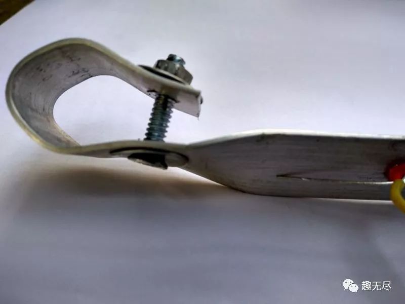
In this project, a sturdy support frame is very important. Because when you ride on bumpy roads or encounter puddles, there will be significant impacts. When the wheel rotates, the magnet on the wheel passes through the Hall Effect sensor on the frame, allowing data collection.
If the device is not securely installed, the display shown by the Arduino will deviate when the bicycle is in motion. Additionally, I don’t want my beloved Arduino to fall off during operation due to installation issues or the use of substandard materials.
Therefore, for safety reasons, I decided to use aluminum tape. Aluminum tape is not only easy to cut and drill but also corrosion-resistant and inexpensive, making it a great choice for makers.
The project also requires some nuts (with washers) and bolts to secure them to the frame, as they must be firmly placed on the chassis.
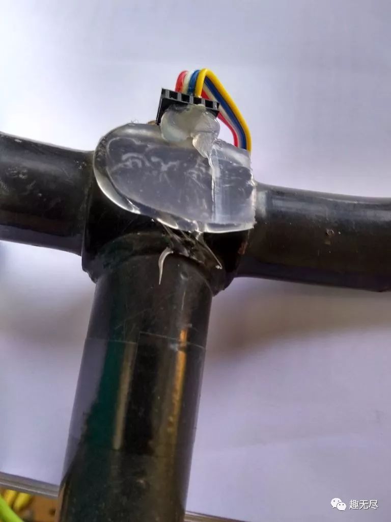
Another important part is that these electronic components must be properly isolated from the frame. Hot glue is a good choice, as it can also help dampen the display.
Sensor and Magnet
Speed measurement relies on this part. The method is to place a magnet on the tire and add a Hall Effect sensor on the frame. Each time the magnet passes the sensor, the Arduino can calculate speed and distance.
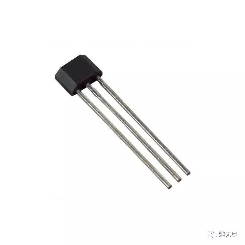
This project uses the classic A3144 Hall Effect sensor. When a specific magnetic surface is oriented correctly, the output of the sensor will be pulled low. Orientation is very important because external magnetic fields will not affect the output.
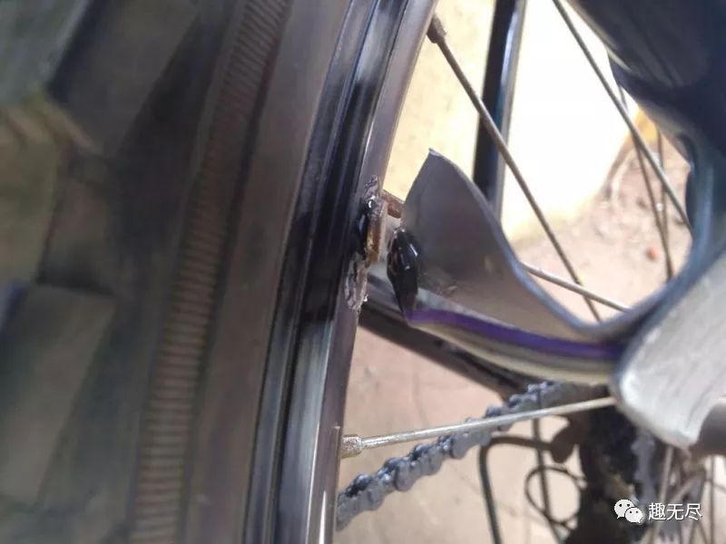
The correct orientation is shown in the figure. The Hall Effect sensor requires a 10k pull-up resistor. In this project, I used a 20k pull-up resistor available in the Arduino.
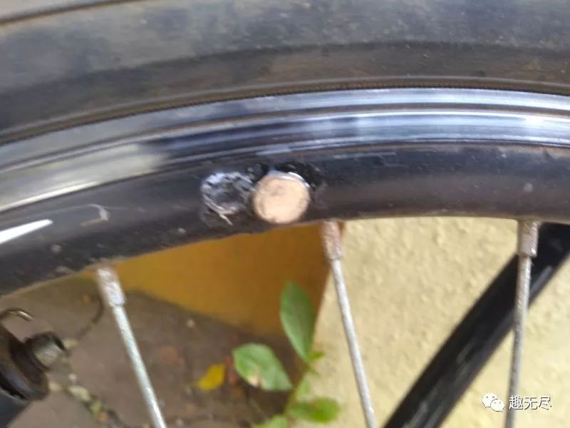
The placement of the magnet is also important. Placing it too far may lead to inconsistent readings or loss of data during rotation, while placing it too close may cause the magnet to contact the sensor, which is not ideal. If you observe closely, there will be some tilt between the wheel and the axle, which will affect the shell and the trough.
Display
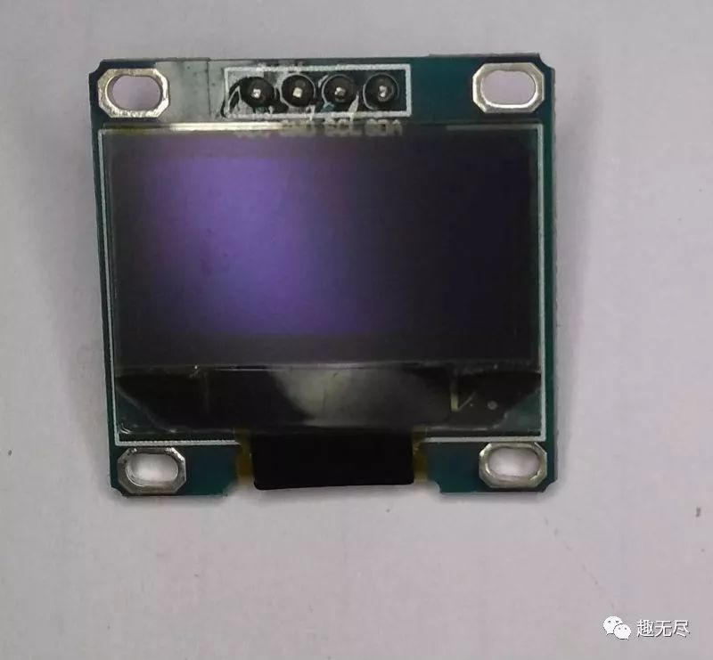
The display is optional, but you need it to show speed, mileage, and real-time acceleration. The display I used is a 0.96-inch OLED display, using I2C as the communication protocol between the slave and master devices.
As shown in the figure, the Arduino automatically switches between three modes.
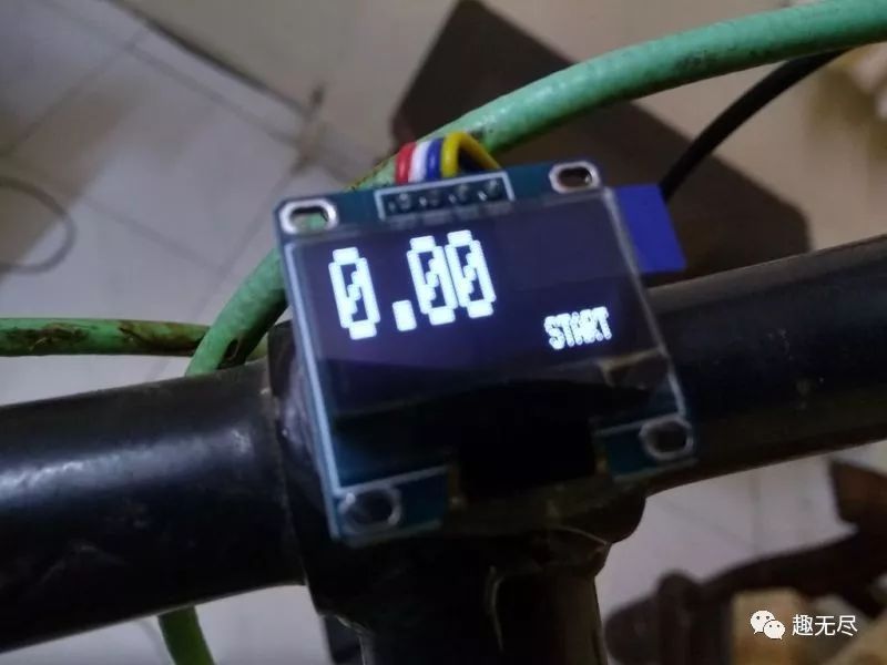 1. Arduino just started and successfully booted.
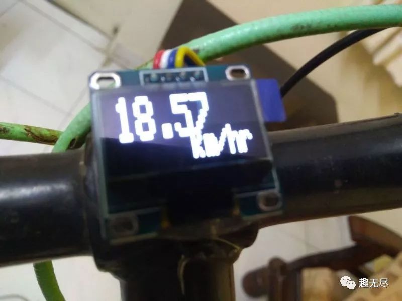 2. Speed unit in km/hr. This mode is displayed during motion and automatically shuts off after stopping.
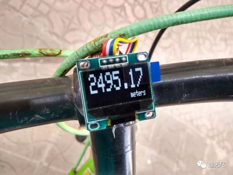 3. Displays the distance traveled in meters. Once the motion stops, the Arduino switch will display the mileage for 3 seconds.
This system is not perfect. It needs to be in motion to display the mileage and other metrics, and it requires your improvement.
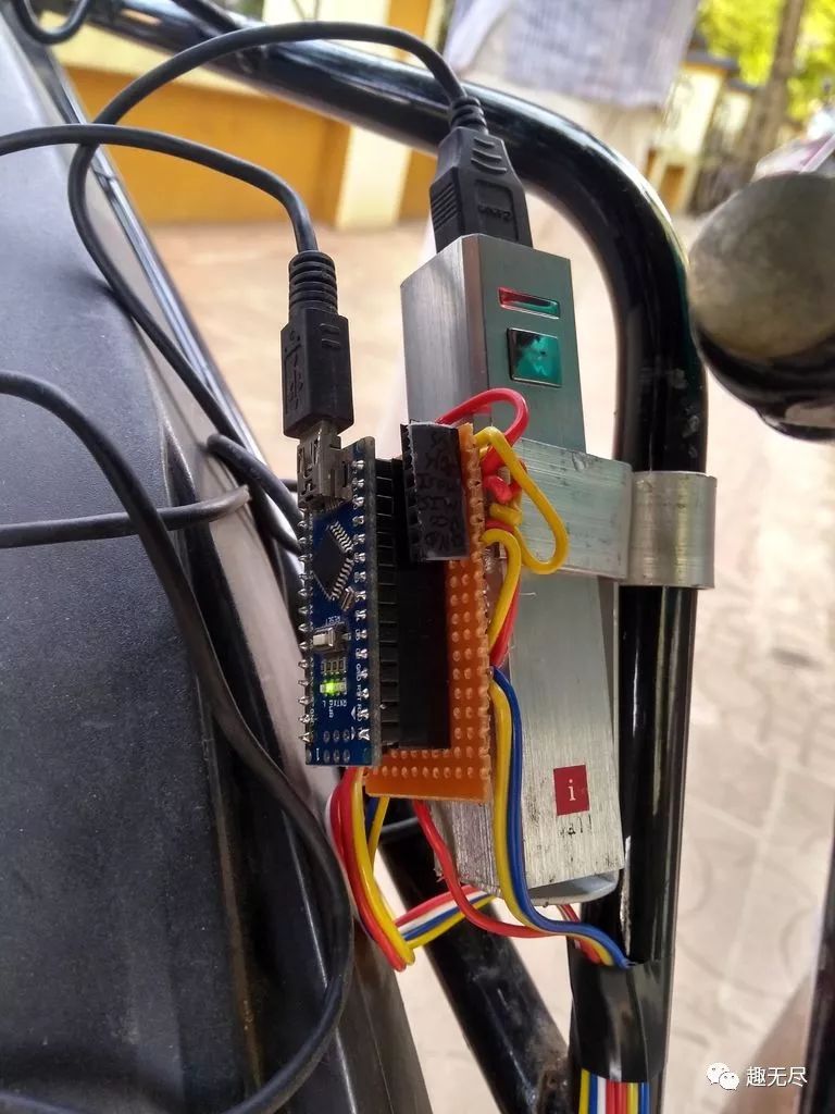
Power Supply Issues
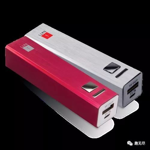
The power supply used in this project is relatively bulky, as shown in the figure. To facilitate charging, I decided to use a power bank as the power supply and connect the USB power line from the power bank to the Arduino Nano using a Mini USB cable.
Choosing the right battery is important; it should be easy to install. I used a rectangular one that is easy to secure.

Many power banks on the market are designed in a somewhat foolproof manner. To save power, if the current consumption does not exceed a certain threshold, the power bank is designed to turn off the output. I set the threshold to at least 200-300 mA.
The maximum current consumption of the circuit does not exceed 20mA. Therefore, most power banks will automatically turn off the output. That’s why I chose a power bank that supports low current consumption.
Brake Light (Optional)
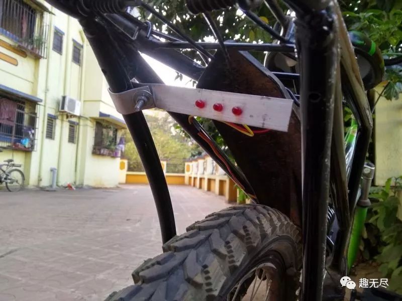
I decided to add a brake light as an additional feature. The question is how to make my light turn on automatically when braking? Experiments showed that if the braking system decelerates (which also means if I calculate acceleration and the result is negative), the brake light can be turned on. It will light up as soon as I stop pedaling.
This is really cool! The brake light draws power directly from pin 2 of the Arduino Nano.
Code
I programmed using the Arduino IDE. The initial goal was to record parameters to an SD card. However, that would require using three libraries: SD.h, Wire.h, and SPI.h. These would occupy 84% of the memory, and the IDE warned me of stability issues. Before long, the Nano would crash and freeze for a while. Restarting would lead to the same problem.
So I gave up on the SD part and commented out the related lines. If someone can solve this issue, that would be great.
For detailed code explanations, please download from the project library.https://maker.quwj.com/project/102
via instructables.com/id/DIY-Cycle-Speedometer/
Links in the article are clickable, and you can check the original article at the end.

More exciting content
DIY “pop” sound control switch with Raspberry Pi
Make a laser cat toy with ESP8266
Make a fully automatic color sorter with Arduino
Raspberry Pi 3 Model A+ released
DIY rechargeable 18650 lithium battery pack with unlimited expansion
Make an LED text scrolling display with Arduino