
Source: This article is written by RT-Thread community member Meng Qiannian, click the link at the end to read the original text for the source.
Introduction
The GPU, or Graphics Processing Unit, is the core of modern graphics cards. In the era before GPUs, all graphics rendering was done by the CPU, which had to calculate the boundaries, colors, and other data of the graphics and was responsible for writing this data into video memory. Simple graphics were manageable, but as computers evolved (especially games), the complexity of the graphics that needed to be displayed increased, and the CPU began to struggle. Thus, GPUs were developed to relieve the CPU from the heavy burden of graphical calculations, significantly accelerating the speed of graphics display.
A similar evolution has occurred in the realm of microcontrollers. In the early use cases of microcontrollers, there was little demand for graphic displays. Even when there was, it was only for simple displays like 12864, which had minimal computational requirements that the microcontroller’s CPU could handle well. However, with the development of embedded graphics, the graphics computation and display tasks that microcontrollers needed to undertake have increased. The display resolution and color depth of embedded systems have also skyrocketed. Gradually, the CPU of microcontrollers began to struggle with these computations. Therefore, starting from the STM32F429, a peripheral similar to a GPU was added to STM32 microcontrollers, which ST calls the Chrom-ART Accelerator, also known as DMA2D (this article will use this name). DMA2D can provide acceleration in many 2D drawing scenarios, perfectly fitting the functionality of a “GPU” in modern graphics cards.
Although this “GPU” can only provide 2D acceleration and its functionality is very simple compared to a PC GPU, it can already meet the graphic display acceleration needs of most embedded development. With proper use of DMA2D, we can create smooth and stunning UI effects on microcontrollers.
This article will introduce the role of DMA2D in embedded graphic development through practical examples. The goal is to help readers quickly grasp the most basic concepts of DMA2D and learn its fundamental usage. To avoid overly obscure and difficult content, this article will not delve deeply into the advanced features and characteristics of DMA2D (such as detailed descriptions of DMA2D’s architecture, all registers, etc.). For more detailed and professional learning about DMA2D, readers can refer to the “STM32H743 Chinese Programming Manual” after reading this article.
Before reading this article, readers should have a basic understanding of the TFT LCD controller (LTDC) in STM32 and fundamental graphic knowledge (such as framebuffer, pixels, color formats, etc.).
Additionally, besides ST, many other manufacturers also produce MCUs with similar functionality (such as NXP’s PxP designed in the RT series), but these are outside the scope of this article. Interested readers can explore them on their own.
Preparation
Hardware Preparation
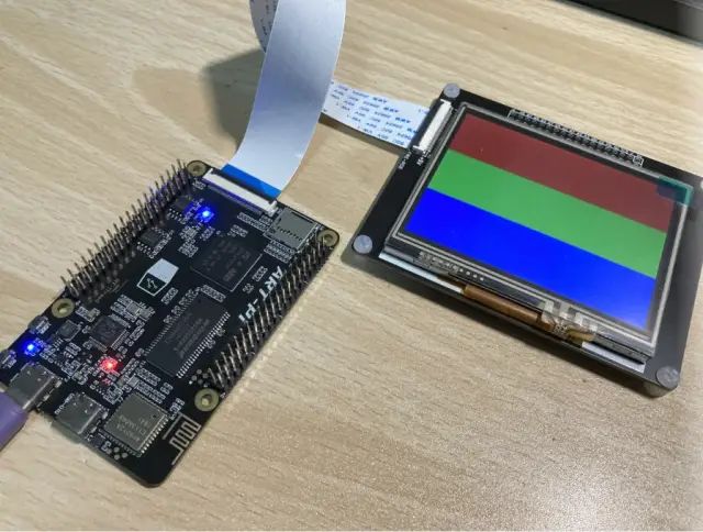
You can use any STM32 development board with DMA2D peripherals to verify the examples in this article, such as STM32F429, STM32F746, STM32H750, etc. The development board used in this article is ART-Pi. ART-Pi is a development board produced by RT-Thread, featuring a powerful configuration with a main frequency of up to 480MHz and 32MB SDRAM. It also has an onboard debugger (ST-Link V2.1), making it very convenient to use, especially suitable for verifying various technical solutions, and it serves perfectly as the hardware demonstration platform for this article.
The display can be any color TFT display, preferably with 16-bit or 24-bit color RGB interface. The display used in this article is a 3.5″ TFT LCD with an RGB666 interface and a resolution of 320×240 (QVGA). In LTDC, the configured color format is RGB565.
Development Environment Preparation
The content and code presented in this article can be used in any development environment you prefer, such as RT-Thread Studio, MDK, IAR, etc.
Before starting the experiments in this article, you need a basic project that drives the LCD display using framebuffer technology. DMA2D must be enabled beforehand to run all the code in this article.
DMA2D can be enabled through this macro (enable it once during hardware initialization):
1// Before using DMA2D, you must enable the DMA2D peripheral first
2__HAL_RCC_DMA2D_CLK_ENABLE();
Introduction to DMA2D
Let’s first take a look at how ST describes DMA2D.
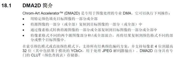
At first glance, it seems a bit obscure, but in simple terms, it offers the following functionalities:
-
Color filling (rectangular area)
-
Image (memory) copying
-
Color format conversion (e.g., YCbCr to RGB or RGB888 to RGB565)
-
Alpha blending
The first two operations are memory-related, while the latter two are computation acceleration operations. Notably, alpha blending and color format conversion can be performed together with image copying, providing significant flexibility.
ST positions DMA2D as a DMA enhanced for image processing functions, and in actual development, we find that the usage of DMA2D is very similar to that of traditional DMA controllers. In some non-graphic processing scenarios, DMA2D can even replace traditional DMA.
It is important to note that the DMA2D accelerators across different ST product lines have slight differences. For example, the DMA2D in the STM32F4 series MCUs does not support ARGB and AGBR color format conversions. Therefore, when needing to utilize a specific function, it is best to consult the programming manual to check if the required feature is supported.
This article only introduces the common functionalities of DMA2D across all platforms.
DMA2D Working Modes
Just like traditional DMA has three working modes: peripheral to peripheral, peripheral to memory, and memory to peripheral, DMA2D, as a DMA, also has the following four working modes:
-
Register to Memory
-
Memory to Memory
-
Memory to Memory with pixel color format conversion
-
Memory to Memory with pixel color format conversion and alpha blending
It can be seen that the first two modes are simple memory operations, while the latter two modes involve memory copying along with color format conversion and/or alpha blending as needed.
DMA2D and HAL Library
In most cases, using the HAL library can simplify code writing and improve portability. However, using the HAL library with DMA2D is an exception. The main issue with the HAL library is that the excessive nesting levels and various safety checks reduce efficiency. When operating other peripherals, the efficiency loss from using the HAL library is not significant. However, for peripherals like DMA2D, which are aimed at computation and acceleration, considering that related operations might be called multiple times within a single screen drawing cycle, using the HAL library can severely degrade the acceleration efficiency of DMA2D.
Therefore, we usually do not use the relevant functions in the HAL library to operate DMA2D. For efficiency, we directly manipulate the registers to maximize the acceleration effect.
Since most scenarios where we use DMA2D frequently change working modes, the graphical configuration of DMA2D in CubeMX also loses its meaning.
DMA2D Scene Examples
1. Color Filling
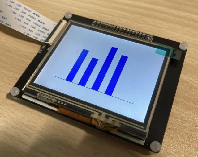
The following image is a simple bar chart:
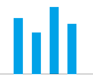
Let’s consider how to draw it.
First, we need to fill the screen with white as the background for the pattern. This step cannot be overlooked; otherwise, the previously displayed pattern on the screen will interfere with our main subject. The bar chart is essentially made up of four blue rectangular blocks and a line segment, which can also be viewed as a special rectangle with a height of 1. Therefore, the drawing of this graphic can be broken down into a series of “rectangle filling” operations:
-
Fill a rectangle the size of the screen with white
-
Fill four data bars with blue
-
Fill a line segment with black, with a height of 1
In essence, drawing a rectangle at any position on the canvas involves setting the color data for the corresponding pixel positions in the memory area. However, since the framebuffer is stored linearly in memory, unless the width of the rectangle exactly matches the width of the display area, the seemingly continuous rectangular areas in memory will have discontinuous addresses.
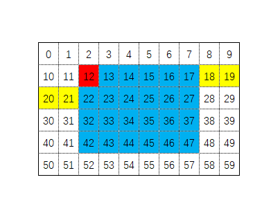
The following image shows a typical memory distribution, where the numbers represent the memory addresses of each pixel in the framebuffer (relative offsets from the starting address, ignoring the fact that one pixel occupies multiple bytes), and the blue area is the rectangle we want to fill. It can be seen that the memory addresses of the rectangular area are discontinuous.
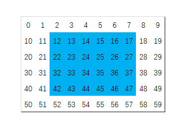
This characteristic of the framebuffer makes it impossible to simply use efficient operations like memset to fill rectangular areas. Typically, we would use a double loop to fill any rectangle, where xs and ys are the coordinates of the top-left corner of the rectangle on the screen, width and height represent the rectangle’s width and height, and color represents the color to fill:
1for(int y = ys; y < ys + height; y++){
2    for(int x = xs; x < xs + width; x++){
3        framebuffer[y][x] = color;
4    }
5}
Although the code is simple, in practice, a large number of CPU cycles are wasted on operations like checking, addressing, and incrementing, with the actual memory writing time being very minimal. This results in decreased efficiency.
In this case, the register-to-memory working mode of DMA2D can come into play, allowing DMA2D to fill the rectangular memory area at extremely high speeds, even if these areas are actually discontinuous in memory.
Continuing with the example illustrated in this image, let’s see how it can be achieved:
First, since we are only filling memory and do not need to copy memory, we need to set DMA2D to work in the register-to-memory mode. This is achieved by setting the [17:16] bits of the DMA2D CR register to 11, as shown in the following code:
1DMA2D->CR = 0x00030000UL;
Next, we need to specify the properties of the rectangle to be filled, such as where the starting address of the area is, the width in pixels, and the height.
The starting address of the area is the memory address of the first pixel in the top-left corner of the rectangle (the address of the red pixel in the image), which is managed by the DMA2D OMAR register. The width and height of the rectangle are managed by the high 16 bits (width) and low 16 bits (height) of the NLR register, as shown in the following code:
1DMA2D->OMAR = (uint32_t)(&framebuffer[y][x]); // Set the starting pixel memory address of the fill area
2DMA2D->NLR  = (uint32_t)(width << 16) | (uint16_t)height; // Set the width and height of the rectangular area
Then, because the memory addresses of the rectangles are discontinuous, we need to inform DMA2D how many pixels to skip after filling one row of data (i.e., the length of the yellow area in the image). This value is managed by the OOR register. A simple method to calculate the number of pixels to skip is to subtract the width of the rectangle from the width of the display area. The implementation code is as follows:
1DMA2D->OOR = screenWidthPx - width; // Set the line offset, i.e., the number of pixels to skip
Finally, we need to inform DMA2D what color to use for the fill and what the color format is. This is managed by the OCOLR and OPFCCR registers, where the color format is defined by the LTDC_PIXEL_FORMAT_XXX macro, as shown in the following code:
1DMA2D->OCOLR   = color; // Set the color used for filling
2DMA2D->OPFCCR  = pixelFormat; // Set the color format, for example, if you want to set it to RGB565, you can use the macro LTDC_PIXEL_FORMAT_RGB565
With everything set, DMA2D now has all the information needed to fill this rectangle. Next, we need to start the DMA2D transfer by setting the 0th bit of the DMA2D CR register to 1:
1DMA2D->CR |= DMA2D_CR_START; // Start DMA2D data transfer, DMA2D_CR_START is a macro with a value of 0x01
Once the DMA2D transfer starts, we only need to wait for it to complete. After the DMA2D transfer is complete, it will automatically set the 0th bit of the CR register to 0, so we can wait for the DMA2D transfer to finish with the following code:
1while (DMA2D->CR & DMA2D_CR_START) {} // Wait for DMA2D transfer to complete
Tip 0: If you are using an OS, you can enable the DMA2D transfer complete interrupt. Then we can create a semaphore and wait for it after starting the transfer, and subsequently release the semaphore in the DMA2D transfer complete interrupt service function. This way, the CPU can do other tasks while DMA2D is working instead of idly waiting here.
Tip 1: Of course, since DMA2D fills memory at an incredibly fast speed, the overhead of task switching in the OS is longer than this time, so even with an OS, we still choose to wait 🙂
To consider the generality of the function, the starting transfer address and line offset are calculated outside the function and passed in. The complete function code we extracted is as follows:
 1static inline void DMA2D_Fill( void * pDst, uint32_t width, uint32_t height, uint32_t lineOff, uint32_t pixelFormat,  uint32_t color) {
 2
 3    /* DMA2D configuration */
 4    DMA2D->CR      = 0x00030000UL;                                  // Configure for register to memory mode
 5    DMA2D->OCOLR   = color;                                         // Set the color used for filling, the format should match the set color format
 6    DMA2D->OMAR    = (uint32_t)pDst;                                // Starting memory address of the fill area
 7    DMA2D->OOR     = lineOff;                                       // Line offset, i.e., the number of pixels to skip, note it is in pixels
 8    DMA2D->OPFCCR  = pixelFormat;                                   // Set color format
 9    DMA2D->NLR     = (uint32_t)(width << 16) | (uint16_t)height;    // Set the width and height of the fill area in pixels
10
11    /* Start transfer */
12    DMA2D->CR   |= DMA2D_CR_START;
13
14    /* Wait for DMA2D transfer to complete */
15    while (DMA2D->CR & DMA2D_CR_START) {}
16}
To make coding easier, we can wrap another function for rectangle filling based on the screen coordinate system we are using:
1void FillRect(uint16_t x, uint16_t y, uint16_t w, uint16_t h, uint16_t color){
2    void* pDist = &(((uint16_t*)framebuffer)[y*320 + x]);
3    DMA2D_Fill(pDist, w, h, 320 - w, LTDC_PIXEL_FORMAT_RGB565, color);
4}
Finally, we try to use code to draw the example chart we started with in this section:
1  // Fill background color
2  FillRect(0,   0,   320, 240,  0xFFFF);
3  // Draw data bars
4  FillRect(80,  80,  20,  120,  0x001f);
5  FillRect(120, 100, 20,  100,  0x001f);
6  FillRect(160, 40,  20,  160,  0x001f);
7  FillRect(200, 60,  20,  140,  0x001f);
8  // Draw X-axis
9  FillRect(40,  200, 240, 1,    0x0000);
Code execution result:
2. Image Display (Memory Copy)
Suppose we are now developing a game and want to display a flickering flame on the screen. Typically, the artist would draw each frame of the flame and place them all in one image asset, as shown below:
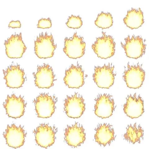
Then we can display each frame of the image in sequence at regular intervals to achieve the “flickering flame” effect on the screen.
We will skip the process of loading the asset file into memory and assume that this asset image is already in memory. Now let’s consider how to display one frame of the image on the screen. Typically, we would implement it like this: first calculate the memory address of each frame’s data, and then copy the data of that frame into the corresponding position in the framebuffer. The code would look something like this:
 1/**
 2 * Copy one frame of the asset to the corresponding position in the framebuffer
 3 * index is the index of the frame in the sequence
 4 */
 5static void General_DisplayFrameAt(uint16_t index) {
 6    // Macro description
 7    // #define FRAME_COUNTS     25  // Number of frames
 8    // #define TILE_WIDTH_PIXEL 96  // Width of each frame (equal to height)
 9    // #define TILE_COUNT_ROW   5   // Number of frames in each row of the asset
10
11    // Calculate the starting address of the frame
12    uint16_t *pStart = (uint16_t *) img_fireSequenceFrame;
13    pStart += (index / TILE_COUNT_ROW) * (TILE_WIDTH_PIXEL * TILE_WIDTH_PIXEL * TILE_COUNT_ROW);
14    pStart += (index % TILE_COUNT_ROW) * TILE_WIDTH_PIXEL;
15
16    // Calculate source address offset
17    uint32_t offlineSrc = (TILE_COUNT_ROW - 1) * TILE_WIDTH_PIXEL;
18    // Calculate framebuffer address offset (320 is the screen width)
19    uint32_t offlineDist = 320 - TILE_WIDTH_PIXEL;
20
21    // Copy data to framebuffer
22    uint16_t* pFb = (uint16_t*) framebuffer;
23    for (int y = 0; y < TILE_WIDTH_PIXEL; y++) {
24        memcpy(pFb, pStart, TILE_WIDTH_PIXEL * sizeof(uint16_t));
25        pStart += offlineSrc + TILE_WIDTH_PIXEL;
26        pFb += offlineDist + TILE_WIDTH_PIXEL;
27    }
28}
As we can see, achieving this effect requires a lot of memory copying operations. In embedded systems, when large amounts of data need to be copied, hardware DMA is the most efficient. However, hardware DMA can only move contiguous data addresses, and here, the data to be copied has non-contiguous addresses in both the source image and the framebuffer, leading to additional overhead (similar to the issue encountered in the first subsection), which prevents us from using hardware DMA for efficient data copying.
Therefore, while we achieved the goal, the efficiency is not high (or rather, did not reach the maximum).
To move data from a specific area of the asset image to the framebuffer as quickly as possible, let’s see how to use DMA2D to achieve this.
First, since we are to perform data copying in memory this time, we need to set the working mode of DMA2D to “memory to memory mode”. This is achieved by setting the [17:16] bits of the DMA2D CR register to 00, as shown in the following code:
1DMA2D->CR = 0x00000000UL;
Next, we need to set the source and destination memory addresses. Unlike the first section, since the source data also has memory offsets, we need to set both the source and destination positions’ offsets simultaneously:
1DMA2D->FGMAR   = (uint32_t)pSrc; // Source address
2DMA2D->OMAR    = (uint32_t)pDst; // Destination address
3DMA2D->FGOR    = OffLineSrc;     // Source data offset (in pixels)
4DMA2D->OOR     = OffLineDst;     // Destination address offset (in pixels)
Then, we also set the width and height of the image to be copied and the color format, which is the same as in the first section:
1DMA2D->FGPFCCR = pixelFormat;
2DMA2D->NLR     = (uint32_t)(xSize << 16) | (uint16_t)ySize;
In the same way, we start the DMA2D transfer and wait for it to complete:
1/* Start transfer */
2DMA2D->CR   |= DMA2D_CR_START;
3
4/* Wait for DMA2D transfer to complete */
5while (DMA2D->CR & DMA2D_CR_START) {}
The final function we extracted is as follows:
 1static void DMA2D_MemCopy(uint32_t pixelFormat, void * pSrc, void * pDst, int xSize, int ySize, int OffLineSrc, int OffLineDst)
 2{
 3    /* DMA2D configuration */
 4    DMA2D->CR      = 0x00000000UL;
 5    DMA2D->FGMAR   = (uint32_t)pSrc;
 6    DMA2D->OMAR    = (uint32_t)pDst;
 7    DMA2D->FGOR    = OffLineSrc;
 8    DMA2D->OOR     = OffLineDst;
 9    DMA2D->FGPFCCR = pixelFormat;
10    DMA2D->NLR     = (uint32_t)(xSize << 16) | (uint16_t)ySize;
11
12    /* Start transfer */
13    DMA2D->CR   |= DMA2D_CR_START;
14
15    /* Wait for DMA2D transfer to complete */
16    while (DMA2D->CR & DMA2D_CR_START) {}
17}
To make it convenient, we can wrap a function to call it:
 1static void DMA2D_DisplayFrameAt(uint16_t index){
 2
 3    uint16_t *pStart = (uint16_t *)img_fireSequenceFrame;
 4    pStart += (index / TILE_COUNT_ROW) * (TILE_WIDTH_PIXEL * TILE_WIDTH_PIXEL * TILE_COUNT_ROW);
 5    pStart += (index % TILE_COUNT_ROW) * TILE_WIDTH_PIXEL;
 6    uint32_t offlineSrc = (TILE_COUNT_ROW - 1) * TILE_WIDTH_PIXEL;
 7
 8
 9    DMA2D_MemCopy(LTDC_PIXEL_FORMAT_RGB565, (void*) pStart, pDist, TILE_WIDTH_PIXEL, TILE_WIDTH_PIXEL, offlineSrc, offlineDist);
10}
Then, we can play each frame of the image in sequence, with a frame interval set to 50 milliseconds, and the target address defined in the center of the framebuffer:
1while(1){
2    for(int i = 0; i < FRAME_COUNTS; i++){
3        DMA2D_DisplayFrameAt(i);
4        HAL_Delay(FRAME_TIME_INTERVAL);
5    }
6}
The final running effect:

3. Image Gradient Switching
Suppose we are developing a photo viewing application, and when switching between two images, directly switching may seem abrupt. Therefore, we want to add a dynamic effect during the switch, and gradient switching (fade in and out) is a common and visually appealing effect.
Let’s use these two images:

Here we need to understand the basic concept of alpha blending. First, alpha blending requires a foreground and a background. The result of blending is akin to looking through the foreground to see the background. If the foreground is completely opaque, the background is entirely hidden; conversely, if the foreground is completely transparent, only the background is visible. If the foreground is semi-transparent, the result is a mixture of both based on the foreground color‘s transparency.
If 1 represents completely transparent and 0 represents opaque, the alpha blending formula is as follows, where A is the background color and B is the foreground color:
1X(C)=(1-alpha)*X(B) + alpha*X(A)
Since colors have three channels (RGB), we need to calculate for all three channels and then combine them:
1R(C)=(1-alpha)*R(B) + alpha*R(A)
2G(C)=(1-alpha)*G(B) + alpha*G(A)
3B(C)=(1-alpha)*B(B) + alpha*B(A)
In the program, for efficiency (as CPU speed for floating-point operations is slow), we typically do not use values in the range of 0-1. Instead, we use an 8-bit integer to represent transparency, ranging from 0 to 255. It is essential to note that a larger value indicates less transparency, meaning 255 is completely opaque, while 0 is entirely transparent (hence the term “opacity”). We can derive the final formula:
1outColor = ((int) (fgColor * alpha) + (int) (bgColor) * (256 - alpha)) >> 8;
Implementing the alpha blending for RGB565 color format pixels:
 1typedef struct{
 2    uint16_t r:5;
 3    uint16_t g:6;
 4    uint16_t b:5;
 5}RGB565Struct;
 6
 7static inline uint16_t AlphaBlend_RGB565_8BPP(uint16_t fg, uint16_t bg, uint8_t alpha) {
 8    RGB565Struct *fgColor = (RGB565Struct*) (&fg);
 9    RGB565Struct *bgColor = (RGB565Struct*) (&bg);
10    RGB565Struct outColor;
11
12    outColor.r = ((int) (fgColor->r * alpha) + (int) (bgColor->r) * (256 - alpha)) >> 8;
13    outColor.g = ((int) (fgColor->g * alpha) + (int) (bgColor->g) * (256 - alpha)) >> 8;
14    outColor.b = ((int) (fgColor->b * alpha) + (int) (bgColor->b) * (256 - alpha)) >> 8;
15
16
17    return *((uint16_t*)&outColor);
18}
Having understood the concept of alpha blending and implemented the blending for a single pixel, let’s see how to achieve image gradient switching.
Assuming the entire gradient transition completes in 30 frames, we need to allocate a buffer in memory equal to the size of the image. We can use the first image (the currently displayed image) as the background and the second image (the upcoming image) as the foreground. Then we set a transparency value for the foreground, perform alpha blending for each pixel, and temporarily store the blending result in the buffer. Once blending is complete, we can copy the data from the buffer to the framebuffer, completing one frame of display. We continue this for the second, third frames, gradually increasing the foreground’s opacity until it becomes fully opaque, thus completing the image gradient transition.
Since each frame requires blending for every pixel from both images, this introduces a massive computational load. It is unwise to leave this to the CPU, so let’s hand this task over to DMA2D.
This time, we will use the blending functionality of DMA2D, so we need to enable DMA2D’s memory-to-memory mode with color blending, corresponding to the value of the [17:16] bits in the CR register being 10:
1DMA2D->CR = 0x00020000UL; // Set working mode to memory to memory with color blending
Next, we set the memory addresses for the foreground, background, and output data, along with the data transfer offsets and the width and height of the image:
1DMA2D->FGMAR = (uint32_t)pFg;               // Set foreground data memory address
2DMA2D->BGMAR = (uint32_t)pBg;               // Set background data memory address
3DMA2D->OMAR  = (uint32_t)pDst;              // Set data output memory address
4
5DMA2D->FGOR  = offlineFg;                   // Set foreground data transfer offset
6DMA2D->BGOR  = offlineBg;                   // Set background data transfer offset
7DMA2D->OOR   = offlineDist;                 // Set data output transfer offset
8
9DMA2D->NLR = (uint32_t)(xSize << 16) | (uint16_t)ySize; // Set image data width and height (in pixels)
Set the color format. Note that when setting the foreground color’s format, if we use a format like ARGB, the alpha channel in the color data itself will influence the blending result. Therefore, we need to set it to ignore the alpha channel in the foreground color data during blending and force the blending transparency.
Output color format and background color format
1DMA2D->FGPFCCR = pixelFormat                // Set foreground color format
2        | (1UL << 16)                       // Ignore the alpha channel in the foreground color data
3        | ((uint32_t)opa << 24);            // Set foreground color opacity
4
5DMA2D->BGPFCCR = pixelFormat;               // Set background color format
6DMA2D->OPFCCR = pixelFormat;                // Set output color format
Tip 0: Sometimes we encounter cases where an image with a transparency channel is displayed over a background; in such cases, we should not disable the alpha channel of the color itself.
Tip 1: In this mode, we can not only perform color blending but also convert color formats simultaneously; we can set the foreground, background, and output color formats as needed.
Finally, start the transfer:
1/* Start transfer */
2DMA2D->CR   |= DMA2D_CR_START;
3
4/* Wait for DMA2D transfer to complete */
5while (DMA2D->CR & DMA2D_CR_START) {}
The complete code is as follows:
 1void _DMA2D_MixColors(void* pFg, void* pBg, void* pDst,
 2        uint32_t offlineFg, uint32_t offlineBg, uint32_t offlineDist,
 3        uint16_t xSize, uint16_t ySize,
 4        uint32_t pixelFormat, uint8_t opa) {
 5
 6    DMA2D->CR    = 0x00020000UL;                // Set working mode to memory to memory with color blending
 7
 8    DMA2D->FGMAR = (uint32_t)pFg;               // Set foreground data memory address
 9    DMA2D->BGMAR = (uint32_t)pBg;               // Set background data memory address
10    DMA2D->OMAR  = (uint32_t)pDst;              // Set data output memory address
11
12    DMA2D->FGOR  = offlineFg;                   // Set foreground data transfer offset
13    DMA2D->BGOR  = offlineBg;                   // Set background data transfer offset
14    DMA2D->OOR   = offlineDist;                 // Set data output transfer offset
15
16    DMA2D->NLR = (uint32_t)(xSize << 16) | (uint16_t)ySize; // Set image data width and height (in pixels)
17
18    DMA2D->FGPFCCR = pixelFormat                // Set foreground color format
19            | (1UL << 16)                       // Ignore the alpha channel in the foreground color data
20            | ((uint32_t)opa << 24);            // Set foreground color opacity
21
22    DMA2D->BGPFCCR = pixelFormat;               // Set background color format
23    DMA2D->OPFCCR  = pixelFormat;                // Set output color format
24
25    /* Start transfer */
26    DMA2D->CR   |= DMA2D_CR_START;
27
28    /* Wait for DMA2D transfer to complete */
29    while (DMA2D->CR & DMA2D_CR_START) {}
30}
Write test code; this time we do not need to wrap the function again:
 1void DMA2D_AlphaBlendDemo(){
 2
 3    const uint16_t lcdXSize = 320, lcdYSize = 240;
 4    const uint8_t cnvFrames = 60; // 60 frames to complete the switch
 5    const uint32_t interval = 33; // 30 frames per second
 6    uint32_t time = 0;
 7
 8    // Calculate output position memory address
 9    uint16_t distX = (lcdXSize - DEMO_IMG_WIDTH) / 2;
10    uint16_t distY = (lcdYSize - DEMO_IMG_HEIGHT) / 2;
11    uint16_t* pFb = (uint16_t*) framebuffer;
12    uint16_t* pDist = pFb + distX + distY * lcdYSize;
13    uint32_t offlineDist = lcdXSize - DEMO_IMG_WIDTH;
14
15    uint8_t nextImg = 1;
16    uint16_t opa = 0;
17    void* pFg = 0;
18    void* pBg = 0;
19    while(1){
20        // Switch foreground/background images
21        if(nextImg){
22            pFg = (void*)img_cat;
23            pBg = (void*)img_fox;
24        }
25        else{
26            pFg = (void*)img_fox;
27            pBg = (void*)img_cat;
28        }
29
30        // Complete the switch
31        for(int i = 0; i < cnvFrames; i++){
32            time = HAL_GetTick();
33            opa = 255 * i / (cnvFrames-1);
34            _DMA2D_MixColors(pFg, pBg, pDist,
35                    0,0,offlineDist,
36                    DEMO_IMG_WIDTH, DEMO_IMG_HEIGHT,
37                    LTDC_PIXEL_FORMAT_RGB565, opa);
38            time = HAL_GetTick() - time;
39            if(time < interval){
40                HAL_Delay(interval - time);
41            }
42        }
43        nextImg = !nextImg;
44        HAL_Delay(5000);
45    }
46}
The final effect:
Performance Comparison
The three examples introduced earlier are common situations I encounter in embedded graphic development. At this point, some friends may ask, how much faster is the DMA2D implementation compared to traditional methods? Let’s conduct a practical test.
Common test conditions are as follows:
-
Framebuffer placed in SDRAM, 320×240, RGB565
-
SDRAM operating frequency 100MHz, CL2, 16-bit bandwidth.
-
MCU is STM32H750XB, main frequency 400MHz, with I-Cache and D-Cache enabled
-
Code and resources on internal Flash, 64-bit AXI bus, speed 200MHz.
-
GCC compiler (version: arm-atollic-eabi-gcc-6.3.1)
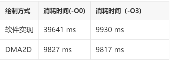
Test Project:Rectangle Filling
-
Draw the chart from the first section of the previous chapter, drawing 10,000 times, and record the results
Test Results:
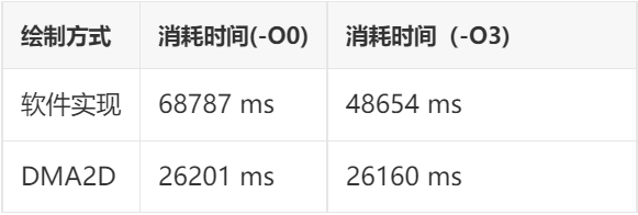
Test Project: Memory Copy
-
Draw the sequence frames from the second section of the previous chapter, 10,000 frames, and record the results
Test Results:
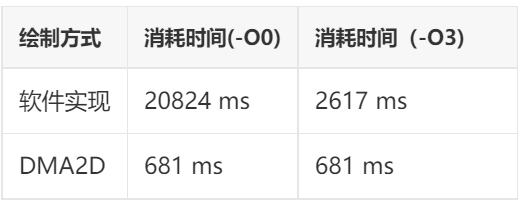
Test Project: Alpha Blending
-
Gradient switching between the two images from the third section of the previous chapter, 100 times, completing 30 frames each time, totaling 3000 frames
-
The blending result is directly output to the framebuffer, without buffering through a buffer
Test Results:
Performance Testing Summary
From the above test results, we can see that DMA2D has at least two advantages:
Firstly, it is faster: In some projects, the speed of DMA2D implementation can be up to 30 times faster than pure software implementation! This is based on tests conducted on the STM32H750 platform with a high main frequency of 400MHz and L1-Cache. If tested on a lower frequency STM32F4 platform without cache, the gap would widen further.
Secondly, it offers more stable performance: The test results indicate that the DMA2D implementation is minimally affected by the compiler optimization level, almost negligible. This means that regardless of whether you use IAR, GCC, or MDK, using DMA2D can achieve similar performance. There will be no significant performance discrepancies when migrating the same code.
In addition to these two obvious results, there is actually a third advantage: the code is simpler to write. DMA2D has relatively few registers and they are quite intuitive. In some cases, using it can be much more convenient than implementing it in software.
Conclusion
The three examples in this article are situations I frequently encounter in embedded graphic development. In reality, there are many other ways to use DMA2D. If interested, you can refer to the relevant content in the “STM32H743 Chinese Programming Manual”. I believe that with the foundation laid in this article, reading the content within will be much more efficient.
Due to the author’s technical limitations, the content in this article cannot achieve 100% accuracy. If there are any errors, please point them out. Thank you.

You can add WeChat 17775982065 as a friend, indicating: company + name, to join the RT-Thread official WeChat group!
👇 Click to read the original text to download the source code and documentation