Author: HYZY
Source: Yanzhi Autonomous Driving
AEB, or Automatic Emergency Braking, monitors the situation of vehicles and pedestrians ahead through radar and cameras. If a potential collision risk is detected, the system will take corresponding warning and braking measures to avoid collisions or reduce the severity of the collision damage.
As an important ADAS active safety feature, the configuration rate of AEB has been continuously increasing in recent years, and it is likely to become a standard feature in the future.
AEB Working Process
The main functions of the AEB system include Pre-Collision Warning (PCW), Emergency Braking (EB), and Pedestrian Protection (PP). The working process is shown in Figure 1.
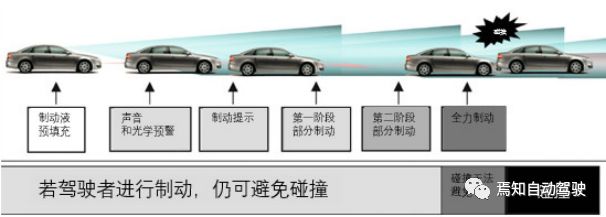
Figure 1 AEB Working Process Diagram
AEB Functions
The sub-functions included in Pre-Collision Warning (PCW), Emergency Braking (EB), and Pedestrian Protection (PP) are shown in Table 1.
Table 1 AEB System Functions
|
Serial Number |
Function |
Sub-Function |
|
1.1 |
Pre-Collision WarningPCW |
Brake PrefillBP(Brake Prefill) |
|
1.2 |
Hydraulic Brake AdjustHBA(Hydraulic Brake Adjust) |
|
|
1.3 |
Potential Distance WarningPDW(Potential Distance Warning) |
|
|
1.4 |
Pre-WarningPW(Pre-Warning) |
|
|
1.5 |
Acute WarningAW(Acute Warning) |
Continuation of Table 1:
|
Serial Number |
Function |
Sub-Function |
|
2.1 |
Emergency BrakingEB |
Emergency Brake AssistEBA(Emergency Brake Assist) |
|
2.2 |
Automatic Emergency BrakingAEB(Automatic Emergency Braking) |
|
|
3 |
Pedestrian ProtectionPP |
Pedestrian ProtectionPP(Pedestrian Protection) |
The purposes and working mechanisms of each sub-function in the above table are shown in Table 2.
Table 2 AEB Sub-Function Purposes and Working Mechanisms
|
Serial Number |
Function |
Purpose |
Working Mechanism |
|
1.1 |
Brake PrefillBP |
Achieve faster braking response |
In general braking systems, to prevent premature wear of the friction pads, a gap is left between the friction pads and the brake disc. This gap causes a delay in emergency braking as it takes time for the two to make contact, affecting the braking distance. Brake Prefill prepares for emergencies by moving the friction pads closer to the brake disc without applying braking force. Under the influence of this function, the system can respond more quickly to the driver’s braking request. |
|
1.2 |
Hydraulic Brake AdjustHBA |
Assist the driver in braking when an emergency braking is triggered |
In cases requiring emergency braking, only a few drivers can effectively perform strong braking, which provides optimal short-distance braking to avoid danger. To compensate for the shortcomings of other types of drivers in this aspect, HBA can detect the driver’s intention to perform emergency braking by monitoring brake pressure signals, thus supplementing the insufficient braking force during emergency braking. The triggering threshold of HBA must be optimized considering extreme conditions to avoid frequent false triggers for drivers with a more “sporty” driving style. The downside is that inexperienced drivers may not trigger this function in emergencies. This function will adjust the HBA triggering threshold based on actual conditions to ensure that most drivers can trigger HBA in emergencies. |
|
1.3 |
Potential Distance WarningPDW |
Remind the driver that the following distance is too small |
The Potential Distance Warning will remind the driver in non-urgent situations, but if the vehicle in front suddenly slows down, the danger level of the situation will quickly escalate. This warning has a prompting nature; if the current situation does not change, no accident will occur. Although there is no danger in this situation, the driver should adjust their driving behavior to maintain a reasonable distance, allowing for a response to avoid an accident if the vehicle ahead suddenly brakes. |
|
1.4 |
Pre-WarningPW |
Gentle visual and auditory alarms |
After the system triggers the Potential Distance Warning, if there is still a collision risk, a Pre-Warning will be triggered. When the warning is activated, the instrument panel displays images and text “Collision Alert”, the target vehicle flashes, and the buzzer sounds three times. |
|
1.5 |
Acute WarningAW |
Strong tactile alarms |
If the driver still does not take any action after the Pre-Warning is triggered, the system will trigger an Acute Warning, reminding the driver through short braking while also displaying text on the instrument panel, and the target vehicle will flash. |
|
2.1 |
Emergency Brake AssistEBA |
Can assist the driver in executing braking in dangerous situations. |
When the driver misjudges the severity of the situation or the braking force is insufficient, the system will provide additional braking force. |
Continuation of Table 2:
|
Serial Number |
Function |
Purpose |
Working Mechanism |
|
2.2 |
Automatic Emergency BrakingAEB |
If the driver does not respond to the warning and the danger level escalates, the system will perform Automatic Emergency Braking |
This includes partial automatic braking AEB-P and medium-speed automatic emergency braking AEB-M. AEB-P is triggered earlier (simultaneously with the Acute Warning) and primarily serves to give the driver more reaction time. If the driver does not respond, it will also reduce the danger of an accident. AEB-M is activated at medium speeds; when the system calculates that a large, uncomfortable deceleration is necessary to avoid a collision, it will trigger this function to automatically brake, reducing the relative speed between the two vehicles as much as possible. |
|
3 |
Pedestrian ProtectionPP |
Avoid or mitigate collisions between the vehicle and pedestrians crossing its lane |
The pedestrian protection function also includes pre-warning, pre-fill, HBA threshold adjustment, and automatic emergency braking sub-functions; specific mechanisms can be referenced above. |
AEB Hardware Architecture
As an ADAS function, AEB hardware includes sensors, controllers, and actuators, as detailed in Figure 2.
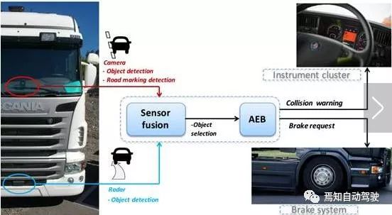
Figure 2 AEB System Composition
1) Sensors
Currently, the mainstream AEB solutions use environmental perception sensors such as millimeter-wave radar and cameras: millimeter-wave radar obtains the distance, speed, and angle of target objects by sending electromagnetic waves and receiving echoes; cameras need to first perform target recognition and then estimate the target’s distance based on the pixel size in the image. There are three specific configuration schemes, as shown in Table 3.
Table 3 AEB Sensor Configuration Schemes
|
Scheme |
Environmental Perception Sensors |
Function/Scene Comparison |
|
|
Millimeter-Wave Radar |
Camera |
||
|
Scheme 1 |
√ |
Urban scene, suburban scene |
|
|
Scheme 2 |
√ |
Urban scene, suburban scene, pedestrian protection |
|
|
Scheme 3 |
√ |
√ |
Urban scene, suburban scene, pedestrian protection |
The performance comparison of the three configuration schemes is shown in Figure 3.
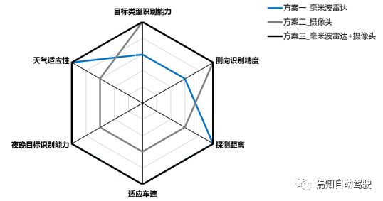
Figure 3 Performance Comparison of AEB Sensor Configuration Schemes
2) Controllers
Currently, AEB controllers are mostly integrated within the sensors (mostly millimeter-wave radar). With the continuous development of intelligent driving technology, AEB control functions will gradually be undertaken by domain controllers.
3) Actuators
Currently, all AEB actuators are ESC systems, and with the gradual mass production of the EHB system (Bosch iBooster), it will become the new AEB actuator, shortening the response time of the actuator and improving the performance of AEB.
AEB Design Philosophy
The frontal collision protection system refers to a series of driving assistance systems developed for longitudinal traffic accidents, of which AEB is part, as shown in Figure 4.

Figure 4 Frontal Collision Protection System
Under current technical conditions, the design purpose of the AEB system is not to guarantee that vehicles will not have rear-end collisions, but to provide responsive assistance and emergency support. Its design philosophy is as follows:
On one hand, when the driver cannot avoid a collision through their own abilities, the system intervenes to reduce the severity of the accident; on the other hand, by reducing speed, it buys the driver more time to take measures such as changing lanes to avoid a collision.
Additionally, the design of AEB must consider the driver’s subjective perception of danger to avoid frequent braking complaints from customers. Of course, in simpler low-speed environments, the AEB system can usually stop the vehicle to avoid a collision.
Figure 5 summarizes the design philosophy of AEB.
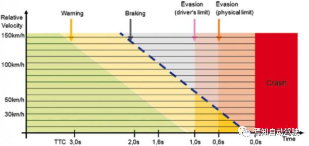
Figure 5 AEB Trigger Time Diagram
[End]
Scan the QR code to join the group