Pain Point Scenario:
-
Do you have an older model of the Weintek touch screen that does not support the official recipe function?
-
Or do you find the built-in recipe inspection window of the software not visually appealing or flexible enough?
-
But you still need to implement a function similar to a “recipe”: storing multiple sets of parameters and being able to quickly call and write to the PLC?
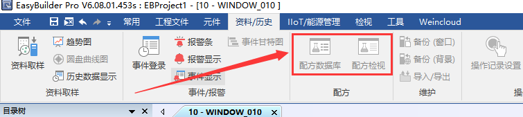
Gray indicates that the recipe function is not supported.
Don’t worry! Today, I will teach you a practical trick: Use the internal addresses (RW) of the touch screen in conjunction with the index register to simulate the recipe function! No need to rely on specific models’ recipe functions, high customization, and interface design at your discretion.

Core Idea:
-
Open up a storage area inside the touch screen: Use the
<span>RW</span>address to store multiple sets of recipe data. -
Implement a recipe “selector”: Use a project selection component in conjunction with the index register to point to the currently selected recipe group.
-
Establish a bidirectional transmission channel: Use the data transmission function to read and write between the internal recipe data of the touch screen and the actual control registers of the PLC.
Below is a detailed step-by-step example using a simple recipe containing 5 parameters:
Step 1: Build the recipe data storage area (inside the touch screen)
-
Plan the addresses: Determine how many data items your recipe contains (5 in this example). Reserve continuous
<span>RW</span>address blocks for each set of recipe data. For example:
-
Recipe Group 1:
<span>RW0</span>(Data 1),<span>RW1</span>(Data 2),<span>RW2</span>(Data 3),<span>RW3</span>(Data 4),<span>RW4</span>(Data 5) -
Recipe Group 2:
<span>RW5</span>(Data 1),<span>RW6</span>(Data 2) …<span>RW9</span>(Data 5) -
Recipe Group 3:
<span>RW10</span>(Data 1) …<span>RW14</span>(Data 5) -
… and so on.
-
Key: The data item addresses for each recipe group must be continuous, and groups must be arranged in order.
Create input components:
-
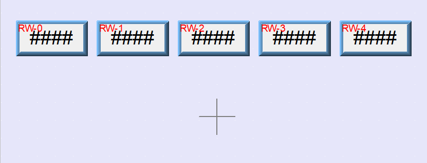
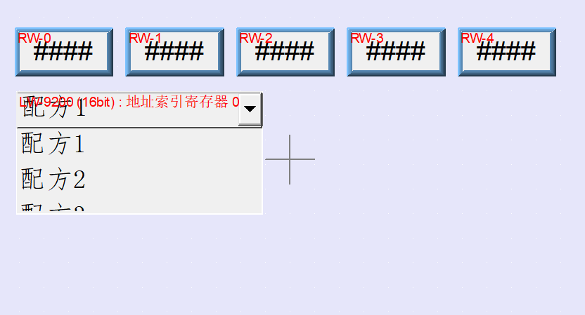
Place 5 numeric input components on the screen.
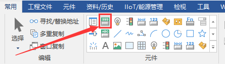
-
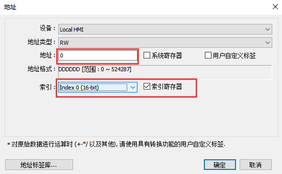
Set their read addresses and write addresses to
<span>RW0</span>,<span>RW1</span>,<span>RW2</span>,<span>RW3</span>,<span>RW4</span>. -
Function: This set of components is used to display and edit the 5 parameter values of the currently selected recipe group. The addresses
<span>RW0~RW4</span>correspond to the first data block of the currently selected group. -
Check the index register and selectIndex 0 (16-bit).
Step 2: Implement the recipe group selector (Key! Application of the index register)
-
Add a project selection component: Place a project selection component on the screen.
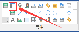
-
Configure the project selection:
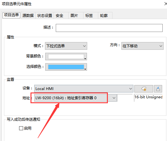
-
Number of items: Select 5.
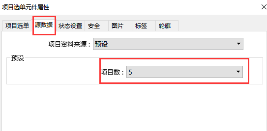
-
<span>Item list</span>: Input your recipe group names, such as “Recipe 1”, “Recipe 2”, “Recipe 3″… Each name occupies one line, with Recipe 1 corresponding to 0, Recipe 2 corresponding to 5, and so on.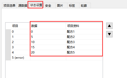
-
<span>Automatic offset principle</span>: When you select “Recipe 2” in the project selection, the value of LW9200 becomes 5. At this point, the 5 input components on the screen (addresses still RW0~RW4) will automatically map to RW(0+5) ~ RW(4+5), that is, RW5~RW9! This is the storage location of the second recipe. Similarly, when selecting “Recipe 3”, the actual access will be RW10~RW14.
-
Select address: This is key! Select an address index register 0 address (
<span>LW9200</span>). The value of this address will represent the index of the currently selected recipe group in the list.
Step 3: Write recipe data to PLC (Download recipe)
-
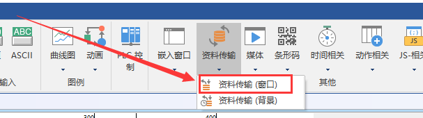
Add a data transmission button: Place a data transmission (window) button and name it “Download Recipe to PLC“.
-
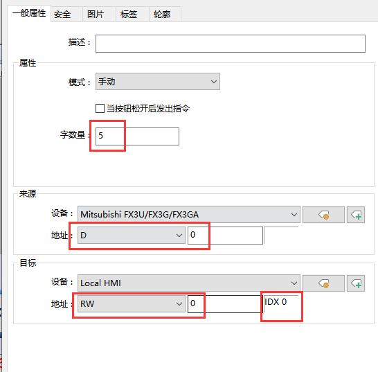
Configure data transmission:
-
Word count: Set to
<span>5</span>(the number of your recipe parameters). -
Source address: Set to RW0, plus the index register 0.
-
Target address: Select
<span>D0</span>.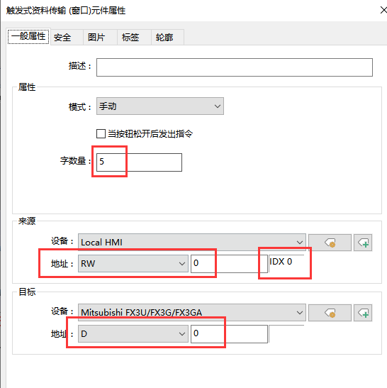
-
Function: Clicking this button will write the currently selected recipe group determined by index register 0 to the actual 5 parameter values, writing them all at once to the PLC’s
<span>D0~D4</span>registers.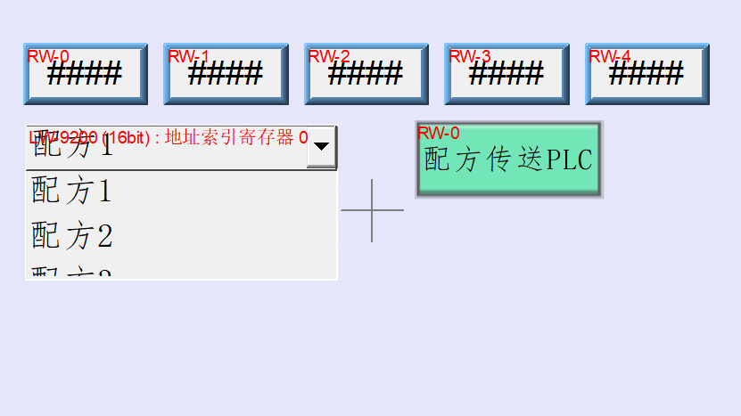
Step 4: Read PLC data back to the touch screen (Load recipe)
-
Add a data transmission button: Place another
<span>data transmission (window)</span>button and name it “Read Recipe from PLC“. -
Configure data transmission:
-
Word count: Set to
<span>5</span>(the number of your recipe parameters). -
Source address: Select
<span>D0</span>.
-
Target address: Set to RW0, plus the index register 0.
-
Function: Clicking this button will read the current values of the PLC’s
<span>D0~D4</span>registers into the storage location of the currently selected recipe group determined by index register 0, making it easy to save the current PLC state as a new recipe or modify an existing recipe.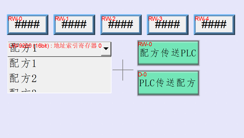
Step 6: Display PLC register status (optional, for monitoring)
-
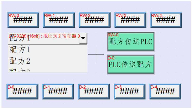
Add display components: Place 5 numeric display components on the screen.
-
Set addresses: Set their read addresses to the actual PLC register addresses
<span>D0</span>,<span>D1</span>,<span>D2</span>,<span>D3</span>,<span>D4</span>.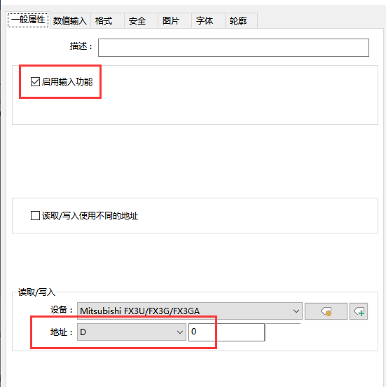
-
Function: Display the actual values of these 5 parameters in real-time from the PLC, making it easy to compare with the data of the currently selected recipe.
Summary of Operation Process:
-
Select a recipe: Select the desired recipe group (e.g., “Recipe 2”) through the project selection. At this point, the
<span>RW0~RW4</span>input boxes display the parameters of Recipe 2 (actually stored in<span>RW5~RW9</span>). -
Modify the recipe (optional): Directly modify the parameter values of Recipe 2 in the input boxes (modifying the values of
<span>RW5~RW9</span>). -
Download the recipe: Click the “Download Recipe to PLC” button. The system will automatically write the parameters of Recipe 2 (
<span>RW5~RW9</span>) to the PLC’s<span>D0~D4</span>. The PLC program can then use this new set of parameters to operate. -
Save the PLC state as a recipe (optional): Click the “Read Recipe from PLC” button. The system will automatically read the current values of the PLC’s
<span>D0~D4</span>registers into the corresponding currently selected recipe group (e.g., Recipe 2) at the<span>RW</span>addresses (<span>RW5~RW9</span>), overwriting the original values. This way, the current state of the PLC is saved as new parameters for Recipe 2.
Advantages and Precautions:
-
Advantages:
-
Model Generality: Does not rely on the official recipe function of the touch screen, allowing older models to implement it.
-
Interface Freedom: Input/display components and button layouts are fully customizable, aesthetically pleasing and flexible.
-
Clear Principles: Based on address offset, easy to understand and maintain.
-
Precautions:
-
Address Planning: Ensure clear planning of the
<span>RW</span>address area, ensuring that each group of recipe addresses is continuous and that there is enough space reserved. Avoid conflicts with other functions using<span>RW</span>addresses. -
Index Register: Ensure that the “Select Address” of the project selection (index register, such as
<span>LW9200</span>) is set correctly and uniquely. -
Transmission Quantity: The “Read/Write Quantity” set in data transmission must strictly match the number of your recipe parameters.
Give it a try! Mastering this method of using internal addresses and index registers to achieve “pseudo-recipe” functionality will allow you to break through the limitations of touch screen models and create a recipe operation interface that better meets your needs. Use it flexibly and think outside the box!

 Scan the code to get the most comprehensive Mitsubishi/Siemens PLC case programs. The editor has worked hard to organize these programs, so if you need them, grab them quickly for future reference!