This article is excerpted from the live recording of Senior Software Architect Yang Wenbo’s “Walking with Masters: Entering Scott Meyers’ C++ World”.
First, let’s review the common implementations of MMIO in embedded C programming. Here, we select two representative embedded MCU solutions: Espressif ESP32 and NXP LPC55.
The Espressif ESP series is a popular IoT solution based on a Bluetooth WiFi integrated module. Its official development framework, Espressif IoT Development Framework, has a high number of stars on GitHub and boasts an active community:
esp-idf (https://github.com/espressif/esp-idf)
Its blinky is implemented as follows:
#elif CONFIG_BLINK_LED_GPIO

static void blink_led(void)
{
    /* Set the GPIO level according to the state (LOW or HIGH)*/
    gpio_set_level(BLINK_GPIO, s_led_state);
}

static void configure_led(void)
{
    ESP_LOGI(TAG, "Example configured to blink GPIO LED!");
    gpio_reset_pin(BLINK_GPIO);
    /* Set the GPIO as a push/pull output */
    gpio_set_direction(BLINK_GPIO, GPIO_MODE_OUTPUT);
}

#endif

void app_main(void)
{
    /* Configure the peripheral according to the LED type */
    configure_led();

    while (1) {
        ESP_LOGI(TAG, "Turning the LED %s!", s_led_state == true ? "ON" : "OFF");
        blink_led();
        /* Toggle the LED state */
        s_led_state = !s_led_state;
        vTaskDelay(CONFIG_BLINK_PERIOD / portTICK_PERIOD_MS);
    }
}
The program first configures a GPIO, and then in a while loop, toggles the GPIO high and low, with the working function being <span>gpio_set_level()</span>. Observing its implementation:
static esp_err_t gpio_output_enable(gpio_num_t gpio_num)
{
    GPIO_CHECK(GPIO_IS_VALID_OUTPUT_GPIO(gpio_num), "GPIO output gpio_num error", ESP_ERR_INVALID_ARG);
    gpio_hal_output_enable(gpio_context.gpio_hal, gpio_num);
    esp_rom_gpio_connect_out_signal(gpio_num, SIG_GPIO_OUT_IDX, false, false);
    return ESP_OK;
}

// ... ...

esp_err_t gpio_set_level(gpio_num_t gpio_num, uint32_t level)
{
    GPIO_CHECK(GPIO_IS_VALID_OUTPUT_GPIO(gpio_num), "GPIO output gpio_num error", ESP_ERR_INVALID_ARG);
    gpio_hal_set_level(gpio_context.gpio_hal, gpio_num, level);
    return ESP_OK;
}

int gpio_get_level(gpio_num_t gpio_num)
{
    return gpio_hal_get_level(gpio_context.gpio_hal, gpio_num);
}
It is noted that the macro <span>GPIO_CHECK</span> appears repeatedly in many functions.
#define GPIO_CHECK(a, str, ret_val) ESP_RETURN_ON_FALSE(a, ret_val, GPIO_TAG, "%s", str)
#define GPIO_IS_VALID_OUTPUT_GPIO(gpio_num) (((1ULL << (gpio_num)) & SOC_GPIO_VALID_OUTPUT_GPIO_MASK) != 0)
/**
 * Macro which can be used to check the condition. If the condition is not 'true', it prints the message
 * and returns with the supplied 'err_code'.
 */
#define ESP_RETURN_ON_FALSE(a, err_code, log_tag, format, ...) do {
        if (unlikely(!(a))) {
            ESP_LOGE(log_tag, "%s(%d): " format, __FUNCTION__, __LINE__, ##__VA_ARGS__);
            return err_code;
        }
    } while(0)
Repeated calls violate the DRY (Don’t Repeat Yourself) principle: The code wrapped by the <span>GPIO_CHECK</span> macro repeatedly checks whether the GPIO’s <span>port</span> number is within a reasonable range. If not, it prints an error message at runtime and returns an error. However, at runtime, each GPIO configuration function calls it, and every function that operates on GPIO, such as <span>gpio_set_level</span>, also calls it.
Entering the <span>gpio_ll_set_level()</span><span> function, it is found that the GPIO's </span><code><span>port</span> number is checked again:
/**
 * @brief  GPIO set output level
 *
 * @param  hal Context of the HAL layer
 * @param  gpio_num GPIO number. If you want to set the output level of e.g. GPIO16, gpio_num should be GPIO_NUM_16 (16);
 * @param  level Output level. 0: low ; 1: high
 */
#define gpio_hal_set_level(hal, gpio_num, level) gpio_ll_set_level((hal)->dev, gpio_num, level)
/**
 * @brief  GPIO set output level
 *
 * @param  hw Peripheral GPIO hardware instance address.
 * @param  gpio_num GPIO number. If you want to set the output level of e.g. GPIO16, gpio_num should be GPIO_NUM_16 (16);
 * @param  level Output level. 0: low ; 1: high
 */
static inline void gpio_ll_set_level(gpio_dev_t *hw, gpio_num_t gpio_num, uint32_t level)
{
    if (level) {
        if (gpio_num < 32) {
            hw->out_w1ts = (1 << gpio_num);
        } else {
            HAL_FORCE_MODIFY_U32_REG_FIELD(hw->out1_w1ts, data, (1 << (gpio_num - 32)));
        }
    } else {
        if (gpio_num < 32) {
            hw->out_w1tc = (1 << gpio_num);
        } else {
            HAL_FORCE_MODIFY_U32_REG_FIELD(hw->out1_w1tc, data, (1 << (gpio_num - 32)));
        }
    }
}
During the LED’s on and off process, how many times will the <span>gpio_num</span> be checked? And what does 32 mean? This kind of checking evidently incurs runtime overhead, and the design intent appears somewhat vague in the repeated and slightly different checks of the same parameter.
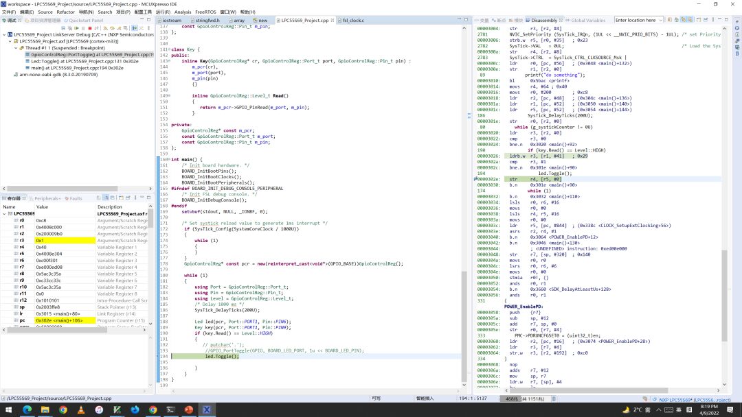
Next, let’s look at the implementation in the NXP LPC55S6x. The NXP LPC55S6x is primarily aimed at applications in industrial IoT and building automation. It is based on ARM Cortex M33 and integrates RAM and ROM along with common peripherals on the chip. I happen to have a third-party LPC55S69 development board: OKdo-E1, from which relevant materials, including NXP’s official IDE, can be downloaded from the link (https://www.okdo.com/getting-started/get-started-with-okdo-e1-board/). Later, I will also demonstrate how to model MMIO using C++ on it.
<span>main.c</span> is implemented similarly:
/*!
 * @brief Main function
 */
int main(void)
{
   //... ...;

    while (1)
    {
        /* Delay 1000 ms */
        SysTick_DelayTicks(500U);
        GPIO_PortToggle(GPIO, BOARD_LED_PORT, 1u << BOARD_LED_PIN);
    }
}
/*!
 * @brief Reverses current output logic of the multiple GPIO pins.
 *
 * @param base GPIO peripheral base pointer(Typically GPIO)
 * @param port GPIO port number
 * @param mask GPIO pin number macro
 */
static inline void GPIO_PortToggle(GPIO_Type *base, uint32_t port, uint32_t mask)
{
    base->NOT[port] = mask;
}
Here, the implementation of <span>GPIO_PortToggle</span> is quite straightforward; it simply assigns a value to the location pointed to by the <span>GPIO_Type</span> pointer at <span>NOT</span>, completing the task without any checks.
Combining with the definition of the <span>GPIO_Type</span> structure:
/** GPIO - Register Layout Typedef */
typedef struct {
  __IO uint8_t B[2][32];                           /**< Byte pin registers for all port GPIO pins, array offset: 0x0, array step: index*0x20, index2*0x1 */
       uint8_t RESERVED_0[4032];
  __IO uint32_t W[2][32];                          /**< Word pin registers for all port GPIO pins, array offset: 0x1000, array step: index*0x80, index2*0x4 */
       uint8_t RESERVED_1[3840];
  __IO uint32_t DIR[2];                            /**< Direction registers for all port GPIO pins, array offset: 0x2000, array step: 0x4 */
       uint8_t RESERVED_2[120];
  __IO uint32_t MASK[2];                           /**< Mask register for all port GPIO pins, array offset: 0x2080, array step: 0x4 */
       uint8_t RESERVED_3[120];
  __IO uint32_t PIN[2];                            /**< Port pin register for all port GPIO pins, array offset: 0x2100, array step: 0x4 */
       uint8_t RESERVED_4[120];
  __IO uint32_t MPIN[2];                           /**< Masked port register for all port GPIO pins, array offset: 0x2180, array step: 0x4 */
       uint8_t RESERVED_5[120];
  __IO uint32_t SET[2];                            /**< Write: Set register for port. Read: output bits for port, array offset: 0x2200, array step: 0x4 */
       uint8_t RESERVED_6[120];
  __O  uint32_t CLR[2];                            /**< Clear port for all port GPIO pins, array offset: 0x2280, array step: 0x4 */
       uint8_t RESERVED_7[120];
  __O  uint32_t NOT[2];                            /**< Toggle port for all port GPIO pins, array offset: 0x2300, array step: 0x4 */
       uint8_t RESERVED_8[120];
  __O  uint32_t DIRSET[2];                         /**< Set pin direction bits for port, array offset: 0x2380, array step: 0x4 */
       uint8_t RESERVED_9[120];
  __O  uint32_t DIRCLR[2];                         /**< Clear pin direction bits for port, array offset: 0x2400, array step: 0x4 */
       uint8_t RESERVED_10[120];
  __O  uint32_t DIRNOT[2];                         /**< Toggle pin direction bits for port, array offset: 0x2480, array step: 0x4 */
} GPIO_Type;
<span>port</span> is of type <span>uint32_t</span>, while the hardware clearly cannot support 4,294,967,296 ports, only up to 2. The comment states that <span>NOT[2]</span> can support multiple pins at once, but for the purpose of lighting, we only wish to toggle one pin at a time. The library does not perform any checks, so the correctness of parameter-related behavior relies solely on the caller. If the caller “accidentally” calls <span>GPIO_PortToggle(GPIO, 3, 1u << BOARD_LED_PIN)</span>, the compilation will pass, but at runtime, nothing may happen, or it may lead to issues such as “turning on the light switch also turns on the air conditioning”.
The above two code snippets are common implementation methods in embedded shared libraries and semiconductor SDKs. They are adequate as semiconductor libraries, fulfilling basic functionalities, but not ideal for industrial-grade or higher-demand applications. The former relies on repeated runtime checks to ensure that user code does not encounter severe issues when using the library interface in various ways. Repetitive code wastes runtime and binary size. The latter library performs minimal checks, directly manipulating registers via a pointer, leaving correctness to the caller. To summarize, the issues that arise when abstracting hardware with the C language are:
-
Changes require multiple modifications, violating the DRY principle;
-
To ensure safety, many redundant checks are added, sacrificing runtime speed and increasing code size;
-
If checks are reduced, safety risks and responsibilities are transferred to the caller, who often lacks a deep understanding of the hardware and may struggle to manage it;
In programming practice, to compensate for the shortcomings of the language-level type system, we must rely on tools, frameworks, and the engineer’s “carefulness” outside the language, all of which increase engineering complexity and maintenance difficulty. The lack of an object-oriented mechanism in the C language also makes it challenging to express certain hardware characteristics, such as: writing registers only, whether the hardware supports dynamic configuration, power supply, and clocking of modules, etc. The Linux kernel has designed a structure to abstract GPIO with numerous pointers and function pointers, while maintaining over 150 types of GPIO. However, this large and comprehensive approach is often not affordable in small embedded frameworks and projects.
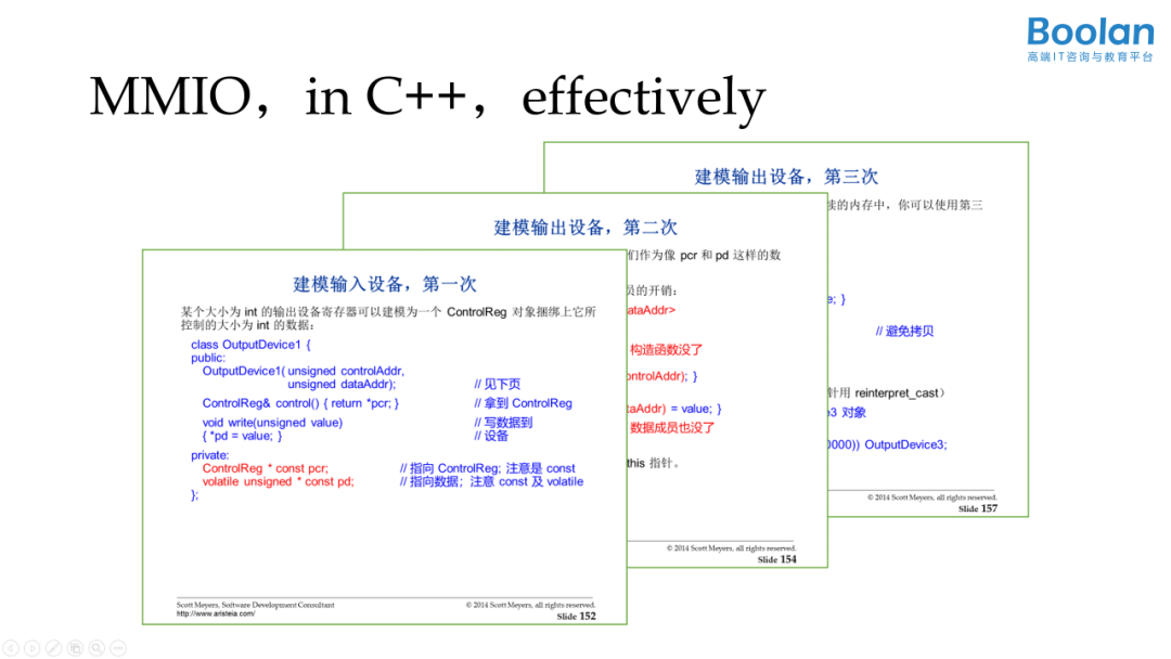
Next, combined with the actual example of LPC55, we will explore the C++ MMIO design idioms summarized by Scott Meyers. Idioms are roughly equivalent to frameworks rather than regulations; they tell us where to place the special handling required for modeling the hardware devices.
Before modeling, let’s summarize what MMIO is. MMIO appears in many embedded SoCs or MCUs, mapping IO devices to fixed locations in the program address space, typically:
-
Input registers and output registers are separated.
-
Control/status registers and data registers are separated.
-
Different bits in the status register express various information, such as readiness or whether the device is enabled.
Moreover, the memory it maps often has characteristics compared to general memory:
-
Atomic read/write may require explicit synchronization.
-
Single bits can sometimes be read-only or write-only.
-
Clearing a bit may require setting it to 1.
-
A status register may control or correspond to more than one data register. For example, bits 0-3 control one data register, while bits 4-7 control another.
Using C++ allows MMIO devices to appear as objects with natural interfaces.
First, the control registers are written as private data members, meaning that the details, especially some characteristics and details of this special memory summarized above, do not need to be of concern to the caller. The operations needed by the caller are abstracted as public member functions. In the lighting example, we only used operations to toggle and read the port, so we will write only two interfaces for now.
There are also two details: the special memory is prefixed with volatile qualifier, as pointed out by CP.200, indicating that this will access hardware that does not follow the C++ memory model; additionally, all functions are inlined, so the speed will be equivalent to the earlier NXP style driver.
class  GpioControlReg {
   public:
      GpioControlReg()
      {
         printf("do something");
      }

      enum class Port_t : uint8_t
      {
         PORT0,
         PORT1
      };

      enum class Level_t : uint8_t
      {
         LOW,
         HIGH
      };

      enum class Pin_t : uint8_t
      {
         PIN6 = 6,
         PIN9 = 9
      };

      inline void PortToggle(Port_t port, Pin_t pin)
      {
         base.NOT[(uint32_t)port] = uint32_t(1u << (uint32_t)pin);
      }

      inline Level_t GPIO_PinRead(Port_t port, Pin_t pin)
      {
         return (Level_t)base.B[(uint8_t)port][(uint8_t)pin];
      }

   private:
      volatile GPIO_Type base;
};
Entering the world of C++, we can immediately replace <span>uint32_t</span> with strong-type enumerations, allowing <span>port</span>, <span>pin</span>, and the read level to have types, enabling the compiler to help us with checks. As long as the caller respects C++’s type system, they can avoid out-of-bounds access or meaningless access. Next, let’s see how the caller invokes this class. Observing the layout of <span>GPIO_Type</span>, we find that it contains several gaps labeled RESERVED_X, totaling over 10 KB. Such a large segment of memory is not suitable for general RAM, as embedded systems typically only have tens of KB of total memory. Here, we will use a C++ language feature: placement new.
In C++, the <span>new</span> expression <span>T *p = new T</span> does two things:
-
Calls a certain
<span>operator new</span><span> function to determine where to place the T object.</span> -
Calls the appropriate T constructor.
<span>operator new</span> is fundamentally not memory allocation, but determining where an object should go. Typically, this results in dynamic memory allocation, such as calling <span>malloc</span><span>. However, sometimes we know where the object should go, such as when we want to place the object at a certain MMIO address or construct it in a specific memory buffer. An implementation of </span><code><span>operator new</span><span> for this might look like:</span>void* operator new(std::size_t, void *ptrToMemory)
{ return ptrToMemory; }
<span>new</span><span>, a widely supported standard form. An expression like </span><code><span>T *p = new T</span><span> will call two functions: </span><code><span>operator new</span><span> and the constructor. The former will pass parameters like this:</span>T *p = new(op new args) T;
T *p = new T(ctor args);
T *p = new (op new args) T(ctor args);
<span>new</span><span>. In the LPC55 blinky example, we use it like this:</span>//...
#include <new>
//...
GpioControlReg* const pcr = new(reinterpret_cast<void*>(GPIO_BASE))GpioControlReg{};
while (1)
{
using Port = GpioControlReg::Port_t;
using Pin = GpioControlReg::Pin_t;
using Level = GpioControlReg::Level_t;
/* Delay 1000 ms */
SysTick_DelayTicks(200U);
if (pcr->GPIO_PinRead(Port::PORT1, Pin::PIN9) == Level::HIGH)
{
putchar('.');
//GPIO_PortToggle(GPIO, BOARD_LED_PORT, 1u << BOARD_LED_PIN);
pcr->PortToggle(Port::PORT1, Pin::PIN6);
}
}
// ...
The official SDK of LPC55 (GNU libstdc++) implements <span>new</span><span> like this:</span>
_GLIBCXX_NODISCARD inline void* operator new(std::size_t, void* __p) _GLIBCXX_USE_NOEXCEPT
{ return __p; }
From the assembly code perspective, this seems to just perform an assignment, but through placement <span>new</span><span>, we get a pointer to pcr with C++ types and semantics, allowing the compiler to impose constraints and checks on it, enabling the caller to build various higher-level abstract objects based on it. Furthermore, placement </span><code><span>new</span><span> will also call the constructor, where GPIO initialization-related code can be included, such as control over clocks and power domains, and application-related checks.</span>
This abstraction is evidently still incomplete; upper-level code using GPIO should not know or remember the GPIO’s port and pin. For general applications, the upper level sets these details during initialization, and thereafter uses them in an object-oriented manner, such as LEDs, buttons, valves, etc. Thus, we can write code like this:
class Led {
   public:
      inline Led(GpioControlReg* cr, GpioControlReg::Port_t port, GpioControlReg::Pin_t pin) :
         m_pcr(cr),
         m_port(port),
         m_pin(pin)
   {}

      inline void Toggle()
      {
         m_pcr->PortToggle(m_port, m_pin);  //GpioControlReg::Pin_t::PIN6
      }

   private:
      GpioControlReg* const m_pcr;
      const GpioControlReg::Port_t m_port;
      const GpioControlReg::Pin_t m_pin;
};
This is how to call it:
Led led(pcr, Port::PORT1, Pin::PIN6);
Key key(pcr, Port::PORT1, Pin::PIN9);
if (key.Read() == Level::HIGH)
{
   led.Toggle();
}
Next, we will run this code on real hardware to observe its behavior and overhead. In MCUXpresso IDE, set the optimization to <span>-O3</span><span>, compile, and download to OKdo-E1, observing in the debugger. Indeed, the compiler has grasped our intent; the constructors of </span><code><span>Led</span> and <span>Key</span> have been completely optimized out, and <span>led.Toggle()</span><span> has become a single assembly line, which cannot be shorter. Thus, our GPIO not only has a more appropriate abstraction but also achieves "you don't pay for what you don't use; what you use, you won't write better code manually":</span>
In practical engineering, the hierarchy and interfaces of classes can be more complex, with many factors and details to consider. For example, how to consider the lifecycle of memory-mapped regions shared by multiple devices; whether to support polymorphism through virtual functions and inheritance, or through metaprogramming; how to prevent users from misusing objects placed in non-MMIO memory areas; how to further reduce redundant code through generic programming, etc. These topics will be further explored in Scott Meyers’ course notes.
Readers interested are welcome to download the example code at gitee(https://gitee.com/yangwenboolean/cpp_mmio_example) and try it on OKdo-E1 or the official LPC55 EVK. Modern C++ is now widely supported by ARM GCC and other commercial compilers, and readers are encouraged to try it on their embedded development boards and share their findings.
The blinky program, such a small example, reflects the advantages of C++ in the embedded field. Let’s summarize a few points:
-
“Direct mapping of language structure to hardware devices”. This not only maps hardware like CPU and memory but also directly maps various external device hardware, which is particularly significant for embedded systems.
-
“Zero-cost abstraction”. The same business logic implemented in C++ often performs better in terms of time and space overhead than in C. Because language-level constraints can provide the compiler with more comprehensive information, it can sometimes achieve “negative overhead”.
-
Embedded technology is generally considered a “latecomer” in the software industry. The C++ language and community’s accumulation and advantages in system programming enable embedded engineers to directly utilize and draw on technologies that have been validated in cutting-edge fields like high-performance cloud computing.
On April 16 at 8 PM, Boolan’s Chief Software Expert Li Jianzhong will discuss “The ‘Way’ and ‘Technique’ for C++ System Engineers’ Advancement”:
1. How to level up in the face of the vast complexity of C++?
2. What are the key points for C++ system engineers’ advancement?
3. How to establish good system software design literacy?
4. How to train and master the core thinking model of C++?

Li Jianzhong
Chief Software Expert, Boolan
Chief Software Expert at Boolan, Chairman of the Global C++ and System Software Technology Conference. Has rich experience and in-depth research in object-oriented design patterns, software architecture, and technological innovation. Lectures on “Design Patterns” and “Object-Oriented Design”, influencing nearly a million software developers and enjoying a prestigious reputation. Served as a Microsoft Most Valuable Technical Expert and Regional Technical Director from 2005 to 2010. Has nearly twenty years of experience in software architecture and product technology.