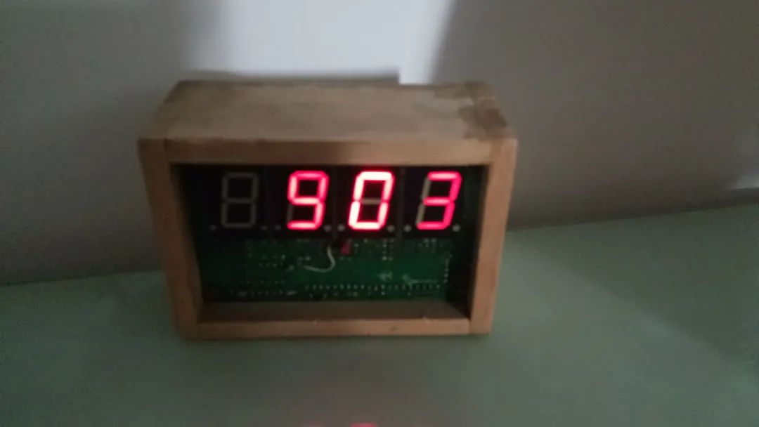
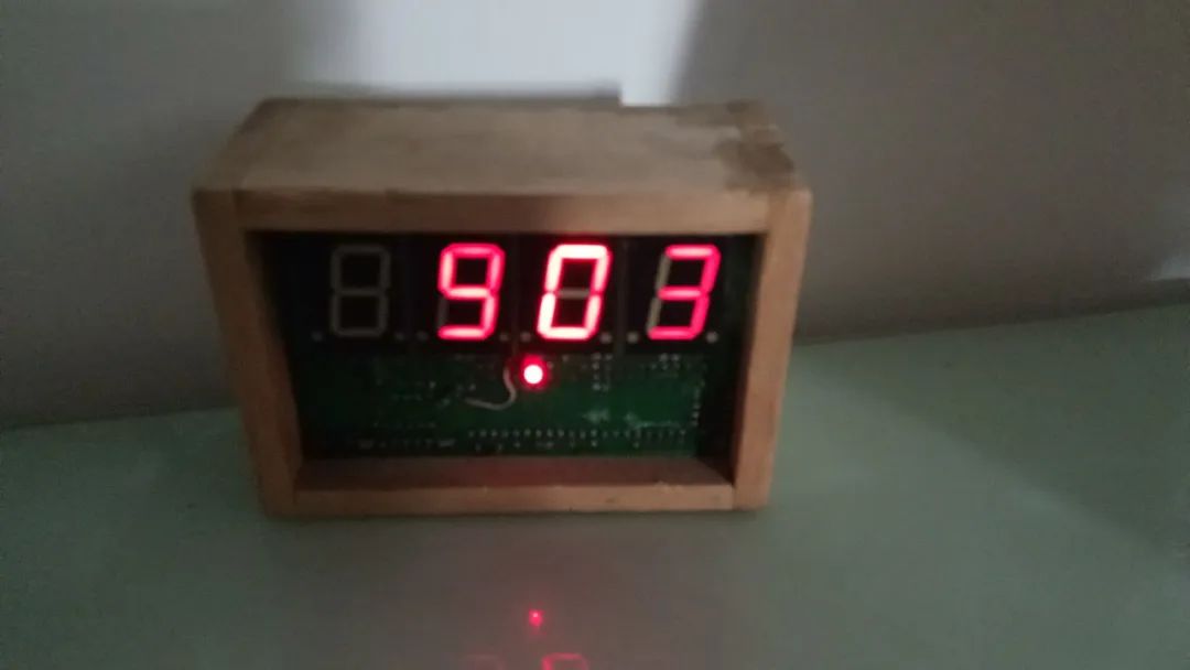
Here is the image:


Strictly speaking, this little gadget was found; I picked up a board.
The reason I picked it up is that it looks new and well-made, and more importantly, the size of the digital tube is relatively large, which is not common for me.
The main chip is the 89S52, quite famous. Although it is not used much now. Looking at the board, I found the power input point, soldered two wires, connected to 5V DC, and the screen displayed four 8s, which went out after a second.
This indicates that the board is good; it does not display because this board alone cannot work; it may only do the display.
Not much use.
Throw it away? I can’t bear it; the four large digital tubes look beautiful when powered on. Also, there is an 89S52.
Disassemble the parts? This board is well-made and has a good appearance, so I can’t bear to do that either.
DIY, highly recommended by the forum master! Since it is a display board, let’s make a clock. There are really few clocks on my desk.
The wooden box is poorly made; I sawed the board and directly used 502 glue. I originally planned to make a panel, which I have been dragging for twenty years; this is my chronic problem.
@wryp
Community Opinions

@DianGongN
AT89S52 is an antique, belonging to the intel51 series. It can still be found on Taobao, making it a perennial favorite.
If the crystal oscillator has 4 pins, it may have temperature compensation and is quite valuable. If it only has 2 pins, it does not have compensation.
I am currently developing industrial instrument products, and the core is the microcontroller; I am still using the 51 series.
The new 51 microcontroller products have rich configurations, including AD DA comparator UART WDT all complete.
Although the core is from the 1980s intel series, it is still useful today.
The original poster replied:
Although it is a found finished board, it is not easy to make it work as I want.
First, map the circuit to see what each IO does, and check the latch truth table online. Which connects to segment display, and which connects to digit display…
Finally, I found that the digital display of this board is non-standard, and I need to design a special code table based on the wiring. I will write a program…
Compile, back then I used Keil. Flash it into the chip, but this board does not have an ISP port.
After some effort, I finally got it running.
After running for a while, I found that the time was inaccurate. By adding and reducing no-operation instructions, I adjusted it until it kept time accurately.
How accurate? The annual error does not exceed 10 seconds. This board’s crystal oscillator is likely a low-temperature drift military product. It may also be that the seasonal temperature changes compensated each other.
The two images I posted indicate that the LED is the second signal, and the light will blink.
The disadvantage of this clock is that it does not know what time it is when the power goes out; it needs to be reset after power is restored.
So, I made another clock that is not afraid of power outages. I will write about it later.

What do you think and feel, everyone?
Please feel free to leave a message!
This article is original to the Mechanical Community; please feel free to share it. If you need to reprint, please contact us for authorization; cover image source: Public Image Library。 For more content, please click below【Read Original】
