
Radio Frequency Identification (RFID) technology, also known as wireless RFID, is a communication technology that can identify specific targets and read and write related data through radio signals without establishing mechanical or optical contact between the identification system and the specific target. It is widely used in enterprise/campus one-card systems, public transport stored value cards, highway tolls, parking lots, community management, etc. This article introduces the use of the FRID-RC522 module.
RFID technology uses wireless radio frequency to perform non-contact bidirectional data transmission between the reader and the radio frequency card to achieve target identification and data exchange.
-
Tag (Tag, i.e. radio frequency card), composed of coupling elements and chips, the tag contains a built-in antenna for communication with the radio frequency antenna.
-
Reader: A device that reads (and can also write) tag information.
-
Antenna: Passes radio frequency signals between the tag and the reader.
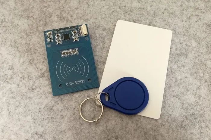
The RFID-RC522 module used in this experiment adopts the MFRC522 chip, uses SPI communication, supports types of cards such as Mifarel S50, S70, Pro, Desfire, etc. The accompanying white card and keychain are S50 cards, each with its own identification (UID).
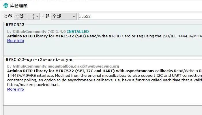
Arduino has an RC522 driver library. Click “Project” – “Load Library” – “Manage Libraries” to find and select the latest version of “MFC522” for installation.
-
Uno R3 Development Board
-
Matching USB Data Cable
-
Breadboard and matching jumper wires
-
RFID-RC522 module and matching S50 white card and special-shaped card
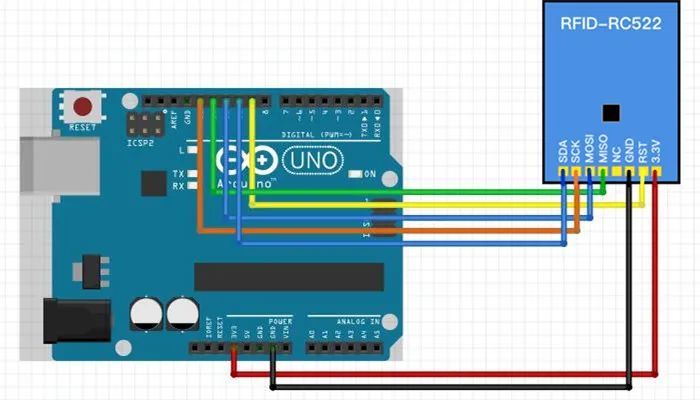
1. Build the circuit diagram according to the schematic.
The RC522 module’s 3.3V and GND are connected to the development board’s 3.3V and GND, respectively. The module’s MOSI, MISO, and SCK are connected to the development board’s SPI interface 11, 12, and 13, respectively. The module’s SDA and RST are connected to the digital pins 10 and 9 of the development board.
The experimental schematic is shown in the figure below:
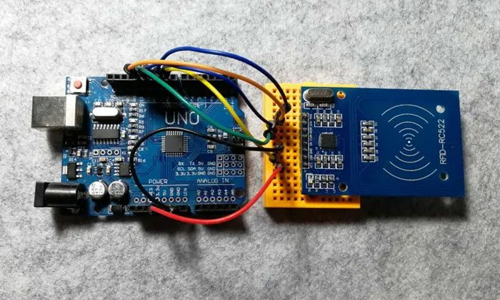
The physical connection diagram is shown in the figure below:
2. Create a new sketch, copy the code below to replace the auto-generated code and save it.
 1#include <SPI.h>
 2#include <MFRC522.h>
 3
 4#define SS_PIN 10
 5#define RST_PIN 9
 6
 7MFRC522 rfid(SS_PIN, RST_PIN);
 8
 9byte nuidPICC[4]; // Store the read UID
10
11void setup() {
12  Serial.begin(9600);
13  SPI.begin();
14  rfid.PCD_Init();
15  Serial.println("RC522 initialization completed...");
16}
17
18void loop() {
19  // Search for new cards
20  if ( ! rfid.PICC_IsNewCardPresent())
21    return;
22
23  // Verify if NUID is readable
24  if ( ! rfid.PICC_ReadCardSerial())
25    return;
26
27  MFRC522::PICC_Type piccType = rfid.PICC_GetType(rfid.uid.sak);
28
29  // Check if it is a MIFARE card type
30  if (piccType != MFRC522::PICC_TYPE_MIFARE_MINI &&
31      piccType != MFRC522::PICC_TYPE_MIFARE_1K &&
32      piccType != MFRC522::PICC_TYPE_MIFARE_4K) {
33    Serial.println("This card type is not supported for reading");
34    return;
35  }
36
37  // Save the read UID
38  for (byte i = 0; i < 4; i++) {
39    nuidPICC[i] = rfid.uid.uidByte[i];
40  }
41
42  Serial.print("Hex UID:");
43  printHex(rfid.uid.uidByte, rfid.uid.size);
44  Serial.println();
45
46  Serial.print("Decimal UID:");
47  printDec(rfid.uid.uidByte, rfid.uid.size);
48  Serial.println();
49
50  // Put the IC card placed in the reading area to sleep, no longer read the card repeatedly
51  rfid.PICC_HaltA();
52
53  // Stop reading card module encoding
54  rfid.PCD_StopCrypto1();
55}
56
57// Hexadecimal output
58void printHex(byte *buffer, byte bufferSize) {
59  for (byte i = 0; i < bufferSize; i++) {
60    Serial.print(buffer[i] < 0x10 ? " 0" : " ");
61    Serial.print(buffer[i], HEX);
62  }
63}
64
65// Decimal output
66void printDec(byte *buffer, byte bufferSize) {
67  for (byte i = 0; i < bufferSize; i++) {
68    Serial.print(buffer[i] < 0x10 ? " 0" : "");
69    Serial.print(buffer[i], DEC);
70  }
71}
3. Connect the development board, set the corresponding port number and development board type, and download the program.
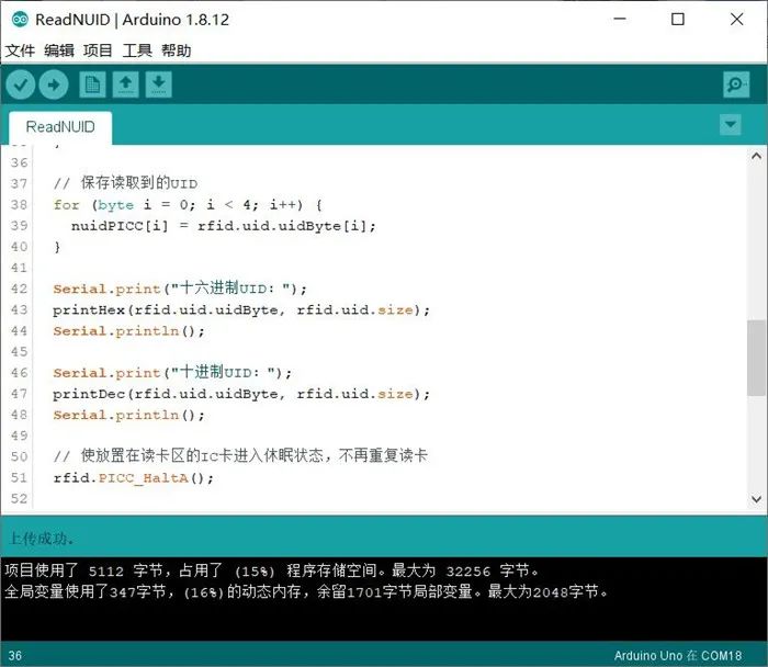
Open the serial monitor, set the baud rate to 9600, which is consistent with the program.Bring the card close to the module antenna sensing area to read the card ID.
Summary of Arduino Basics
Arduino Development Tool – VSCode
If you find this article helpful, please like, share, and comment, it is also a support for me.
Follow the public account “TonyCode” and reply in the background“Improve”, to get the code resources in the article.

Long press to recognize the QR code in the image to follow