24V Brushless DC (BLDC) Motor Sine Wave Drive for Air Purifier Fan
This reference design is an economical, small form factor (SFF), three-phase sine wave driver for brushless DC (BLDC) motors, capable of delivering up to 50W at 24V. The board accepts a 24V input and provides three motor outputs to drive the BLDC motor in a sine wave manner. After receiving speed commands through an IR (infrared) sensor, a microcontroller (MCU) (in this design, the MSP430G2303) is used to externally close the speed loop.
BLDC Motor Sine Drive Features:
· As a 50W, 24V driver, it can drive brushless DC (BLDC) motors in a sine wave commutation manner.
· The MSP430G2303 accepts IR input and closes the external speed loop.
· The DRV10983 uses a proprietary sensorless control scheme to provide continuous sine drive, significantly reducing the pure tone typically generated during commutation.
· Efficiently steps down the power supply voltage to 3.3V through an integrated buck/linear regulator to power internal and external circuits (in this design, the TI MSP430™ MCU).
· The hardware design has been tested at 50W with good thermal performance.
· This design is a tested, readily available hardware and software platform suitable for driving 12V/24V BLDC motors under 50W.
Brushless DC (BLDC) Motor Sine Drive System Design Block Diagram:

Motor Sine Drive Experimental Circuit Board Display:

STM32 Stepper Motor H-Bridge Drive Control Schematic + Source Code
The attached content shares STM32F103VCT6 + stepper motor L6205 H-bridge drive control open-source materials.
What can you learn from the STM32 stepper motor driver program?
1. Basic program architecture: What should go in MAIN and what should go in interrupts.
2. STM32 + DMX512 receiving program (or RS485).
3. Photoelectric encoder program (no open-loop control).
4. FSMC TFT driver program with menu function.
5. Stepper motor microstepping driver program: vector control, acceleration and deceleration control, PWM chopping drive method.
6. Operations of multiple timers, PWM control, external interrupt input, serial port interrupt, and long and short press keys, code protection.
7. How to operate printing printf and TFT LCD debugging programs.
STM32 Stepper Motor Driver Development Board Physical Screenshot:

STM32 Stepper Motor Driver Program Source Code Screenshot:

Infineon Electric Bicycle, Small Electric Vehicle, Motor Control Board + BLDC Motor Driver (Schematic + PCB + Design Notes)
This universal motor driver card is designed for the Infineon XMC4000 microcontroller series CPU board. This satellite card is part of the Infineon hexagonal application suite series, demonstrating the motor control capabilities of the XMC4000 series with the appropriate CPU board.
Motor Control Board Circuit Physical:


Motor Control Board Circuit Features:
· Seamlessly connects to the CPU board via ACT satellite connector.
· 3-phase low-voltage half-bridge inverter using Infineon MOSFET power transistors.
· Gate driver IC with overcurrent detection circuit (ITRIP).
· Measures current using single or three-way shunt (amplified).
· Position sensing via inductive decoders, quadrature encoders, or Hall sensors.
· Input power supply range: 24V +/-20%.
· On-board power supply includes SMPS for 5V generation, with LDO regulator for MOSFET gate driver and decoder excitation (15V) and logic (3.3V).
Motor Control Board Circuit Parameters:

Stepper Motor Driver Schematic + PCB + Driver Source Code + User Guide, etc.
This stepper motor driver is also known as EasyDriver, which can provide approximately 750mA (1.5A total) per phase for bipolar stepper motors. It defaults to 8-step microstepping mode (so if your motor has 200 steps per revolution, using EasyDriver defaults to 1600 steps per revolution). This is a microstepping driver based on the Allegro A3967 driver chip. For the complete specifications of this design, please refer to the A3967 datasheet. Its maximum per-phase current ranges from 150mA to 750mA. The maximum driving voltage that can be used is approximately 30V, including the on-board 5V regulator, so only one power supply is needed. It is cost-effective, priced at just a few dollars, cheaper than making your own circuit board.
Stepper Motor Driver Design Features:
· A3967 Microstepping Driver.
· MS1 and MS2 pins broken out to change microstepping resolution to full, half, quarter, and eighth steps (defaults to eighth).
· Compatible with 4, 6, and 8 wire stepper motors of any voltage.
· Adjustable current control from 150mA/phase to 700mA/phase.
· Power supply range from 6V to 30V. The higher the voltage, the higher the torque at high speeds.
Stepper Motor Driver Schematic Screenshot:

Physical Display:

Stepper Motor Driver Source Code Screenshot:

[Open Source] Multifunctional Stepper Motor/DC Motor Controller Development Board (Schematic + PCB + Sample Programs + Component List)
This is a multifunctional motor control development board that integrates motor control and microcontroller development, capable of driving stepper motors and DC motors, and can also be used as a regular 51 development board. The attachment provides detailed schematics and PCB engineering files for direct manufacturing by the factory. The board uses the powerful and easy-to-use AT89S52 microcontroller as the main control chip, and the motor drive section uses the L298N driver, which can easily handle general motor control, including achieving motor forward and reverse, PWM speed control, etc. In addition, the attachment sample programs provide detailed examples of each function for reference and learning for friends.

Stepper Motor Reference Example Package:

DC Motor Reference Example Package:

Stepper Motor Wiring Method:

DC Motor Wiring Method:

48V 1kW Automotive Three-Phase Brushless DC Motor Driver Design (Schematic, PCB Source Files, Source Programs, etc.)
TIDA-00281 TI reference design is a three-phase brushless DC motor driver suitable for 48V automotive applications. This board is designed to drive motors in the 1kW range and can handle currents up to 30A. This design uses analog circuits combined with C2000 LaunchPad, allowing rotation of three-phase BLDC motors without feedback from Hall effect sensors or quadrature encoders.
Automotive DC Motor Driver System Design Block Diagram:

Three-Phase Brushless DC Motor Driver Circuit Features:
· Speed control of three-phase brushless DC (BLDC) motors without position sensors.
· Control of three-phase power supply through phase voltage and current sensing calibration and filtering feedback.
· Operates over a wide voltage range in a 48V battery system.
· Reverse polarity protection for 12V battery.
Three-Phase Brushless DC Motor Driver Circuit Board PCB Screenshot:

Attachment Content Screenshot:


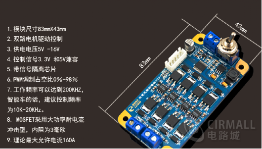
MOS Dual Motor Driver Module BTS7960 Information Summary (Schematic, Test Programs, User Instructions, etc.)
MOS dual motor driver module features:
· 2 motor drive outputs, typical maximum current of 160A per board;
· Added bus driver chip 74LVC245 to enhance signal driving capability while isolating MOSFETs and microcontrollers, protecting the microcontroller chip from direct battery voltage input through MOSFET damage, preventing damage to the microcontroller control pins;
· Added MIC5219 power chip to provide power for the bus driver chip 74LVC245, achieving level matching between the driver chip and the microcontroller.
· Added varistor at the motor output to prevent peak voltage generated during instant motor commutation from damaging other chips;
· The board has 4Xφ3 holes reserved for direct fixation at the rear of the smart car model;
· The board layout has been optimized for high current capacity; it is also more conducive to heat dissipation;
· Driver board operating voltage range: 5V~14V; must not exceed 16V;
· Motor operating frequency range: 0~25KHz; recommended driving frequency range: 5KHz~8KHz;
Physical Display:

Attachment Content Screenshot:

Arduino-Based L293D Motor Driver Board/Motor Circuit + PCB Source Files + Source Code, etc.
Arduino is a great introduction to electronics, and with the motor expansion board, it can become a good robot development platform. Here we introduce a fully functional motor expansion board that can drive various simple to moderately complex projects. This is a commonly used DC motor driver module using the L293D chip for small current DC motor driving. The pins have been made compatible with Arduino, making it easy for enthusiasts to quickly develop based on Arduino.
L293D Motor Driver Board Overview:
This motor driver board is multifunctional and easy to operate, with strong driver library support and functional updates. It is suitable for Arduino beginners, Arduino experimental equipment platforms, Arduino interactive electronics, Arduino robots, etc. It can drive up to 4 DC motors or 2 stepper motors while also driving 2 servos, supporting the latest Arduino UNO, Arduino Mega 2560.
Specific features are as follows:
1. 2 5V servo motor (steering gear) ports connected to Arduino’s high-resolution, high-precision timer – no jitter!
2. Up to 4 bi-directional DC motors and 4 PWM speed control (approximately 0.5% resolution).
3. Control of up to 2 stepper motors for forward and reverse, single/double step control, interleaved or micro-stepping, and rotation angle control.
4. 4 H-bridges: Each bridge of the L293D chip provides 0.6A (peak 1.2A) current with thermal shutdown protection, 4.5V to 36V.
5. Pull-down resistors ensure that the motor remains stopped when powered on.
6. Large terminal blocks make wiring easier (10 – 22AWG) and power supply.
7. Comes with an Arduino reset button.
8. 2 large terminal external power connection terminals ensure separation of logic and motor drive power.
9. Compatible with Mega, Diecimila, & Duemilanove.
Physical connection diagram as screenshot:

L293D Motor Driver Board/Motor Board Circuit Screenshot:


L293D Motor Driver Board Source Code Screenshot:

NXP Smart Car Dual Motor MOSFET Driver
Circuit Introduction
Used for participating in the NXP Smart Car Competition, the motor driver board features dual MOSFETs, which provide larger output and stronger driving capability compared to the BTN79xx series drivers, with faster response.
Components Used
Half-bridge driver IR2184S
MOSFET IRLR7843
Boost B0512S-1W
Display 0.96-inch OLED
Isolation Circuit SN74HC244PW
Function
Controls dual motors with strong driving force, able to handle even the most powerful B car model motors.
Onboard is a 0.96-inch OLED, convenient for displaying parameters during debugging while saving space on the main board.
It has four dip switches and five buttons for parameter input and mode setting.
A buzzer serves as a program prompt flag for debugging.
Design Insights
The smart car driver board mainly consists of three functional parts: boost, half-bridge or full-bridge control, and MOS switch. Understanding these three parts allows for flexible circuit design combinations. For instance, for boosting, I can use LM2577, MC34063, LMR62014, etc., and for the controller, HIP4082 is also fine. Additionally, during layout, it’s crucial to pay attention to trace width due to the high current involved in motor driving; therefore, wide traces of 120mil are advisable, and vias can be opened for thicker solder.
Attachment Content Screenshot:

Smart Car Motor Driver Module Circuit L298N Schematic + PCB Source Files
This is a motor driver module essential for making smart cars. The driver chip used in this module is L298N, which can control 2 DC gear motors.
Welding diagram physical display as follows:

Motor Driver Circuit Schematic Screenshot:

PCB Source Files Screenshot:

60V 45A High-Power Three-Phase Brushless DC Motor Driver with WIFI Support, for Robots and Electric Vehicles
Ultra-high power and strong torque three-phase brushless motor driver. Supports WIFI control.
Main Parameters:
Input voltage 20V~60V.
Maximum current 60A.
Long-term working current 30A.
WIFI: 2.4G.
Operating System Openwrt.
Can be used in fields such as electric doors, treadmills, electric curtains, electric vehicles, robots, lawn mowers, etc.
Some beautiful pictures.


This article is reprinted from Circuit City.