
Mechanical Frontline, National Leader in Mechanical Micro-Education
© Article by Digital Home

This machine has been in my eBay collection for a long time. One day, I accidentally glanced at my collection and suddenly found that the seller had drastically reduced the price to only $15, with a best offer option. You can’t lose buying it for $15, you can’t be deceived for $15. Without further ado, I decisively made the purchase.
According to the very limited information available,this machine is codenamed AN/ASX-2, and is part ofthe non-cooperative identification system developed by the U.S. military for the F4 fighter jet in 1968. The so-callednon-cooperative identification does not use a radio transponder, but ratherdirectly identifies the target type by analyzing the characteristic information of the target. Naturally, such a system has a high possibility of misjudgment. The machine disassembled this time isanalyzing the radar echoes through spectrum analysis to determine the type of the opposing aircraft and judge the type of target. Of course, this equipment is already very old, and today it has completely lost its confidentiality value. Additionally, in 1988, the U.S. military shot down an Iranian passenger plane due to misjudgment (see Iran Air Flight 655 incident), and the U.S. subsequently terminated the development of the non-cooperative identification system (though it is unknown if any secret research continued). Therefore, such equipment has also been completely abandoned and appears on the internet as electronic waste.
The machine I received has aserial number of 001. It is said that this set of equipmentwas produced in only 6 units, and this one is likely the first prototype developed by the U.S. military, and it is very possible that it is the first operational machine since the U.S. began development in 1965. Therefore, I personally feel that its historical value is also considerable. However, it is clear that the machine can no longer operate; several circuit boards are missing, and circuits such as the simulation front end have been dismantled. However, overall, it is still relatively complete. I will share it to broaden everyone’s horizons.
The shell is gray, and nothing can be seen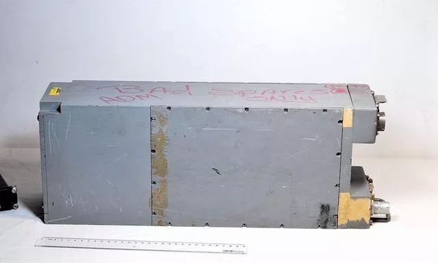 This side has some writing, indicating that the machine is broken and can only be used for parts
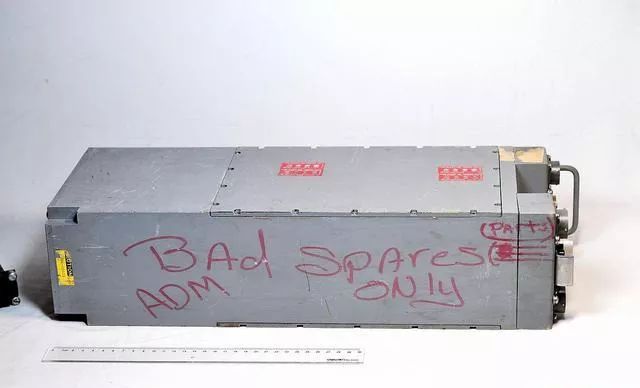 This side has two temperature-sensitive stickers, which are introduced on the back
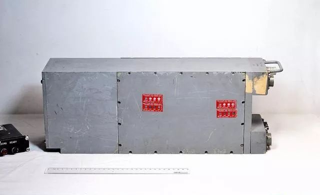 The seller also included a small control box, but it is unknown if it is compatible with the machine
 Number No.001, ASSY M600663-1
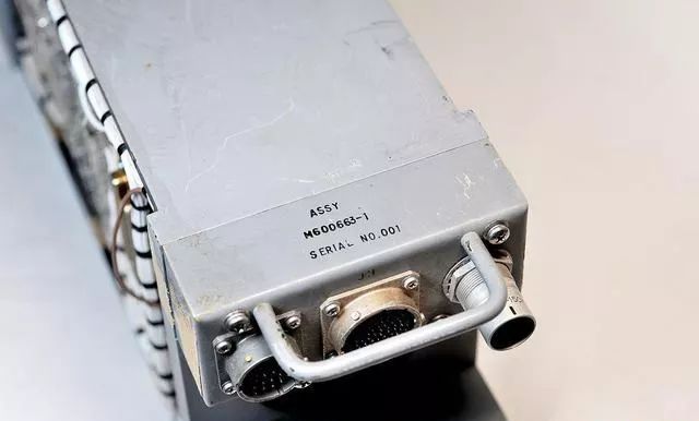 The interface part originally had a fan that has long been removed
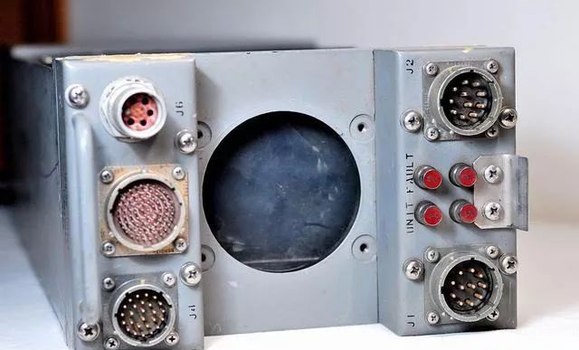 Aviation socket, which also has a coaxial interface; this is the first time I have seen one. It is estimated that the simulated signal from the radar enters here
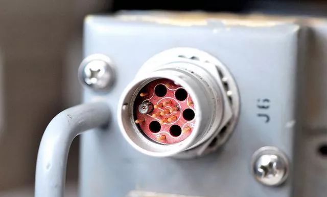 Giant aviation socket
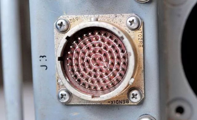 Fault indicator light, which is gold-plated inside
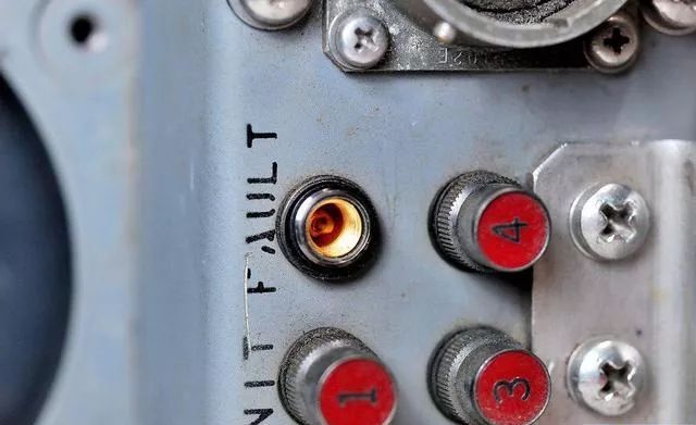 The bulb is an incandescent lamp, and there is still a layer of steel mesh inside the lampshade. Indeed, high-end goods excel in details
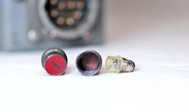 Below, this is thetemperature indicator label, which can be used to detect the maximum temperature during device operation. When the temperature exceeds the corresponding value on the label, the corresponding circle turns black, and it will remain black indefinitely. This way, after operating the device on the aircraft for a period of time, you can know what the highest temperature was.
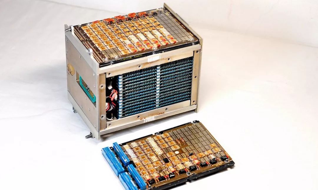
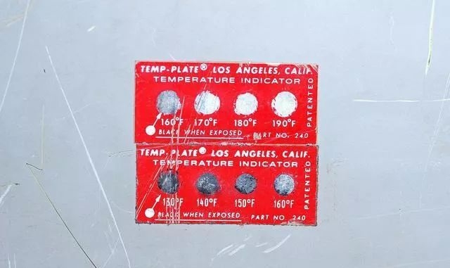 I used a hairdryer for a while, and the 170-degree circle turned blackThe back of the machine hides a huge magnetic core storage module
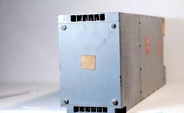 Below, I opened a side panel and saw the complex bus structure inside.。。。
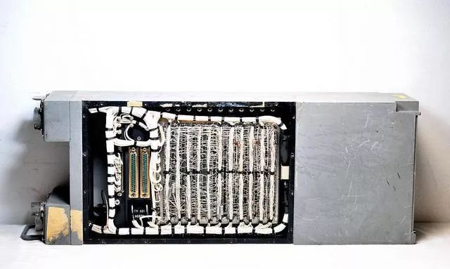
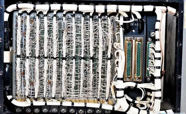 Up close, this isthe circuit manually connected with special winding tools. Since it does not require printed circuits and is convenient for modification and prototype production, it is very common in early computers and military equipment
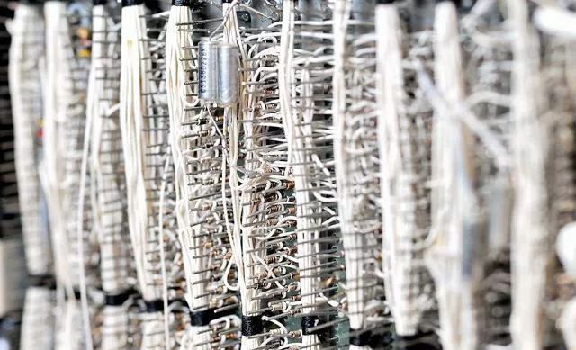 These two interfaces may be used for debugging or programming (pure guess)
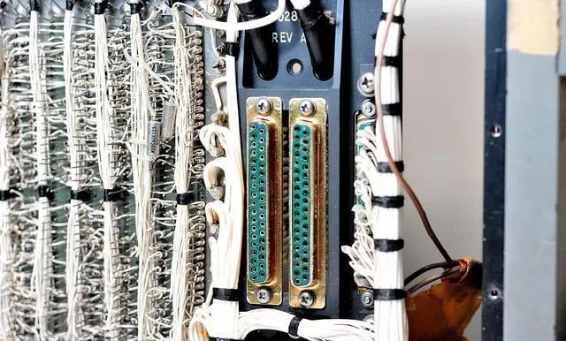 Below, I opened the cover on the other side… and found that many boards were missing; it seems impossible to get the machine running again.But fortunately, there are still 7 circuit boards left
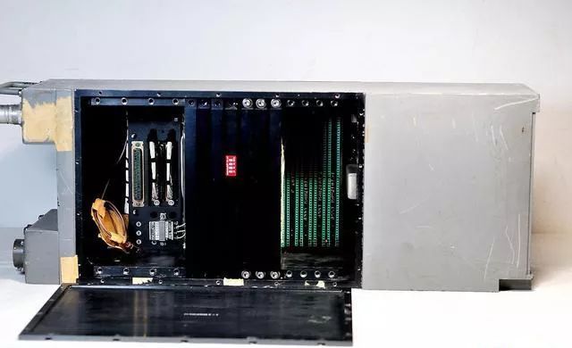 From the side, there are quite a few chips on the circuit board
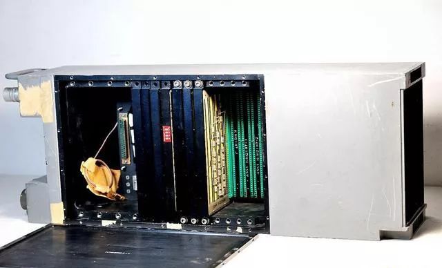 Change the angle
 There is a 14MHz crystal oscillator here, which seems to be active, providing clock for the system
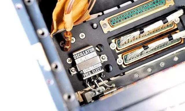 There is also one that has been disassembled
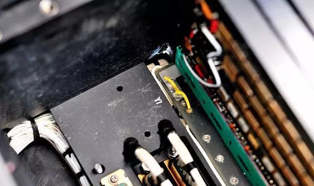
Now, I pulled out the first board, and it was simply stunning It’s hard to imagine thatin 1968, the Americans already had surface mount technology. Back then, Armstrong had yet to land on the moon, and Dongfanghong had yet to reach the sky; most Chinese engineers had never even heard of integrated circuits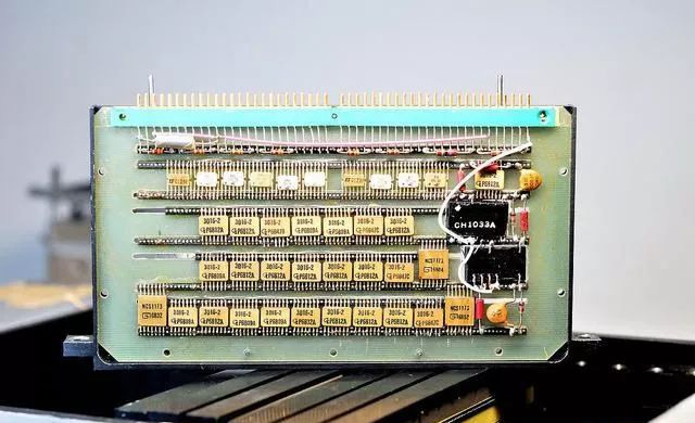 However, the back.。。Uh
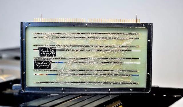 The wires are too whimsical.。。It should also be used for prototype production, just to verify functionality.The flying wires used here are also something I have seen for the first time; it seems to be a silver-plated wire wrapped in a very thin layer of transparent insulating material, looking almost naked
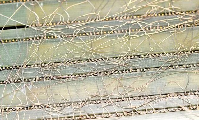
The chips are made by General Instruments, and their purpose is unknown. They look like cache-like things. This company was later acquired by Microchip (the company that produces PIC microcontrollers).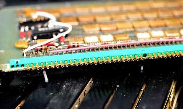 Below, I took out the second board. The circuit board is entirely made of stainless steel, embedded in an aluminum frame.This board is filled with small-scale integrated circuits, which should be used to implement logical functions
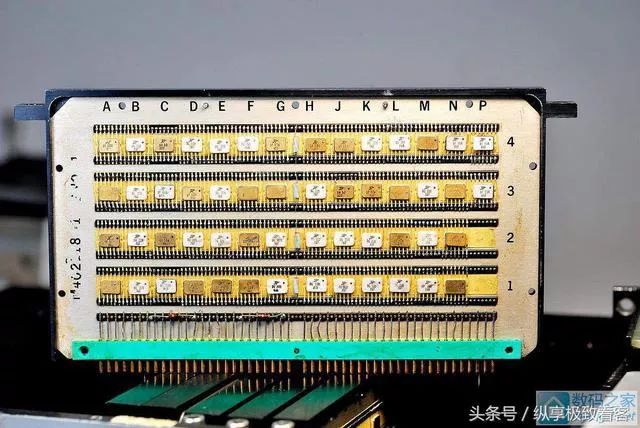 The back is also quite whimsicalUpon closer inspection, it is found that the power and ground connections of each chip are connected to the power bus hidden inside the board, and the remaining pins also use special silver-plated flying wires
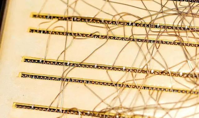 The third board, besides the surface mount chips, has several through-hole chips from Fairchild Semiconductor. Of course, the model cannot be found
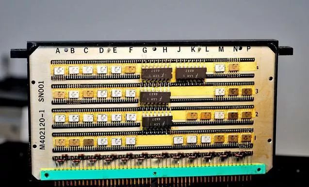 This board has components on both sides
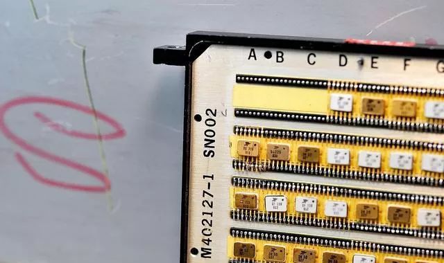 In fact, it is two stainless steel circuit boards embedded in the same aluminum frame on both sides
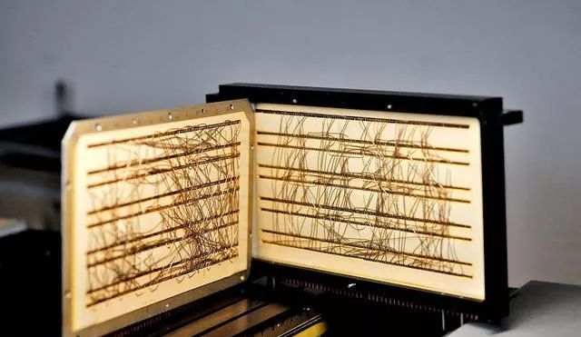 The circuit board number is also 001
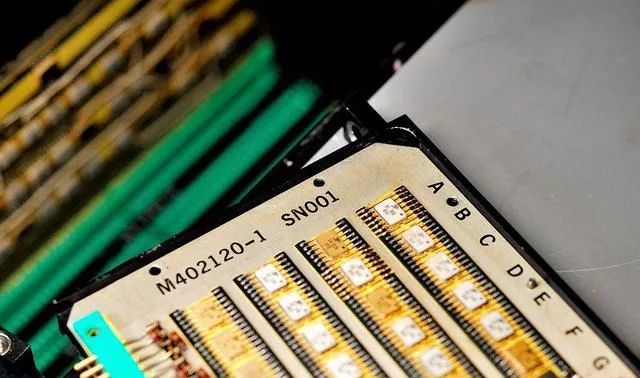 The other boards are actually quite similar, all with a lot of small-scale integrated circuitsThis one is numbered 002
 The board also has a temperature label to observe the internal temperature of the machine
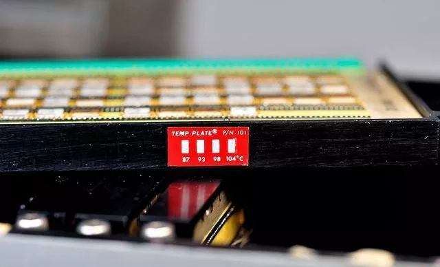 This board clearly has issues, and it has been manually wired for debugging
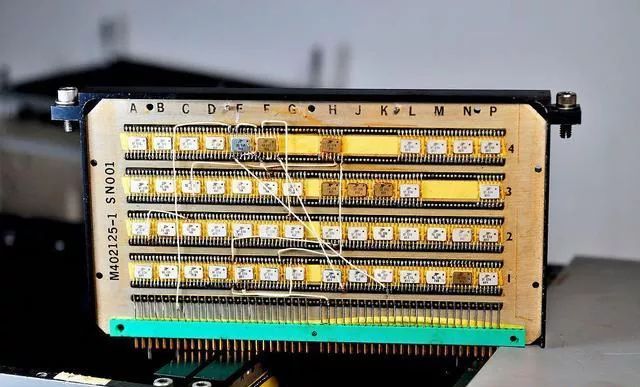
 This one is the same.
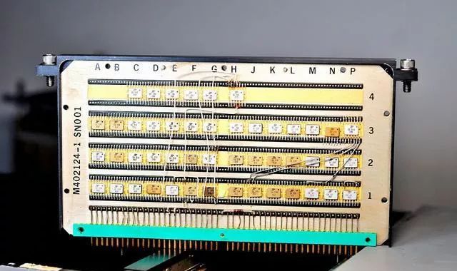
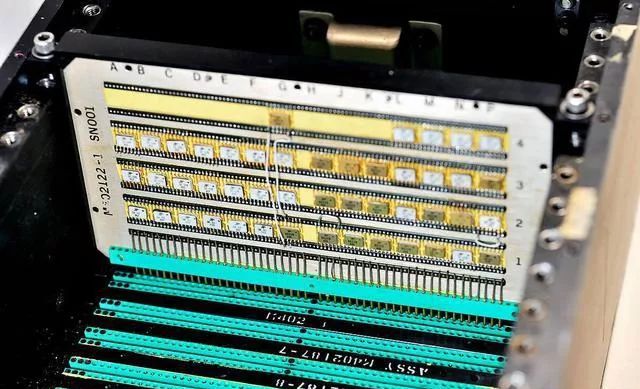
 All remaining circuit boards have been taken out, and each board has different positioning pins at various locations to prevent incorrect insertion
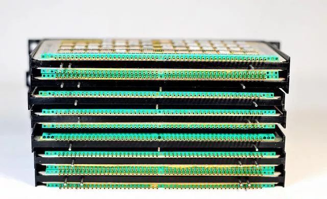 From the side
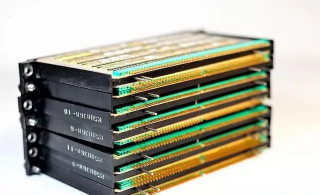 Empty chassis, with each socket labeled with the corresponding module number
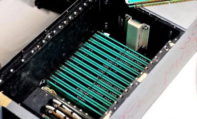 All circuit boards together
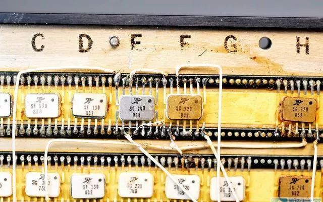
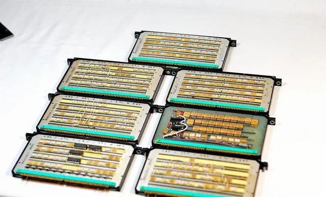 Now, let’s take a look at the details. The small-scale integrated circuits used on these circuit boards are produced by American Sylvania (now known for making light bulbs). This company was also one of the earliest manufacturers of integrated circuits, but it fell behind later…
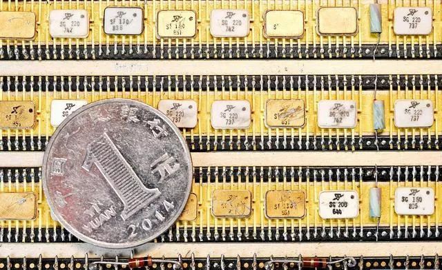
It must be mentioned that Sylvania successfully developed TTL integrated circuits in 1963, making it one of the first manufacturers to produce TTL integrated circuits in the world (earlier than the famous Texas Instruments and the 74 series chips). The integrated circuits used in this machine are the first generation TTL integrated circuits from Sylvania. This mini packaging is called flat pack, which was common in the 1960s and widely used in military equipment.
The SGxxx in the picture represents logic gates, and SFxxx represents flip-flops. According to the information, SG220 is a NAND gate, SG200 is an 8-input NAND gate, and SF130 is a 50MHz J-K flip-flop.
 There’s not much to see inside the host, let’s open the cover on the back of the machine to see what’s inside
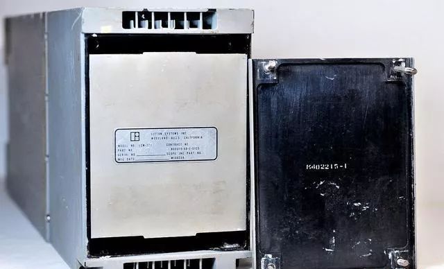
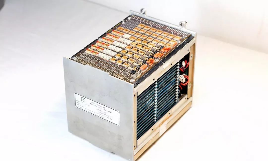
The nameplate indicates that this module is produced by Litton. This company is a well-known American arms manufacturer, with products including navigation systems, fire control systems, aerospace, and even spacesuits for NASA.There’s not much valuable information on the nameplate, but according to the data, this is a 32KB magnetic core storage module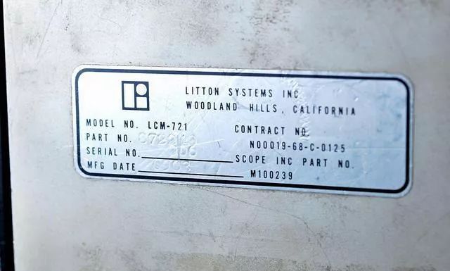 After disassembling
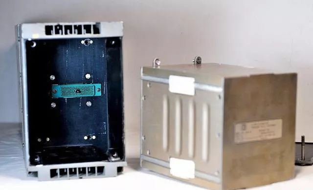 Looking at it separately, it says bad memory, indicating that the memory module is also broken haha
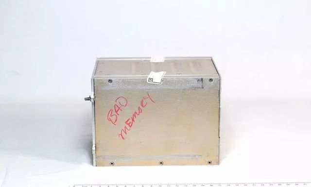 The entire module is completely wrapped in metal and has a seal
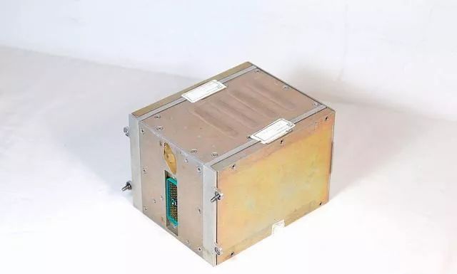 The seal says Litton Company / Navigation and Control Division, last date July 12, 1972
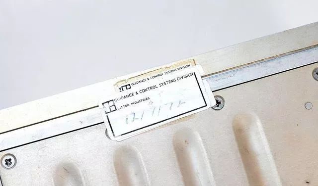 I originally didn’t want to break the seal, but to see what it looks like inside, I had to painfully disassemble it…After removing the side, I saw a bunch of magnetic core storage boards stacked together
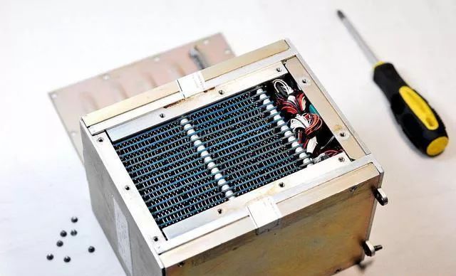 Change the angle
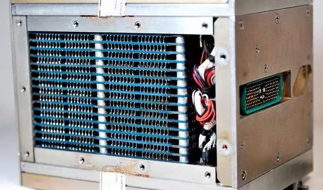 The cover on top should have something, continue to disassembleJust opened the lid, a flash of golden light passed by. I’m going blind.。。。。
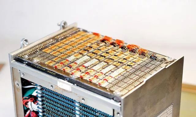 All golden chips, neatly arranged… I have to say, so far, this is the most beautiful circuit I have ever seen
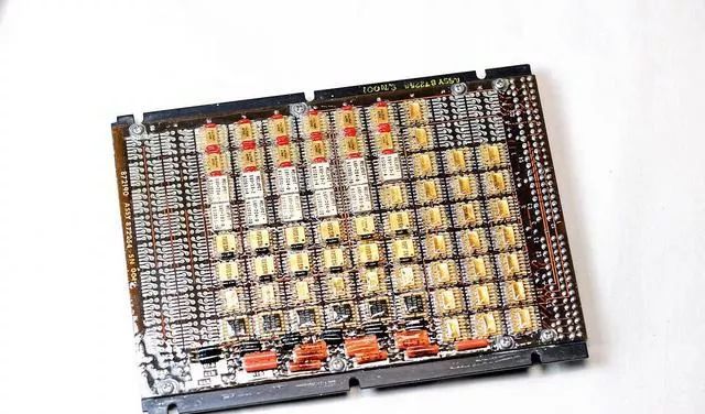 Taking it down, this is the front
 The back also has a layer, with two boards attached to a steel plate on either sideThe front circuit board number is 001
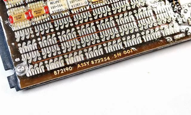 Fairchild’s chip
 These are ceramic resistors
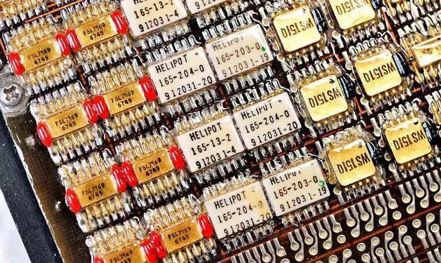 Resistors
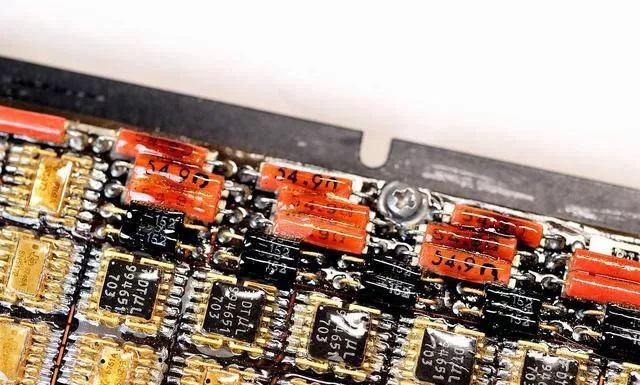 The white ones are Motorola chips
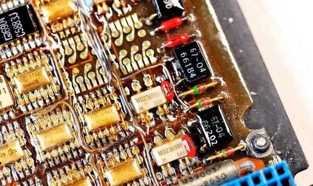 SN5400, the famous TI appears! This is a flat pack packaged 74 series TTL chip, produced in the fourth week of 1968. 54 represents military-grade chips, and 5400 is naturally the famous 4 NAND gate It is said that in 1968, such a chip cost $20, so the entire system must have been quite expensive
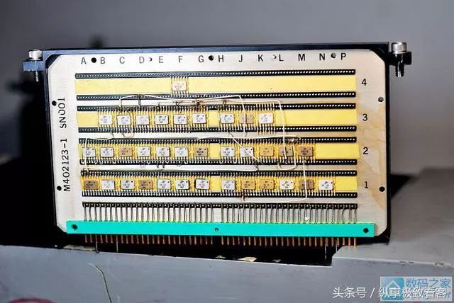
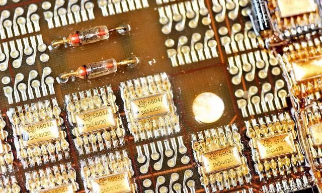 The other side of the module also has a similar circuit boardThe front is completely the same, probably the front circuit for magnetic core reading and writing
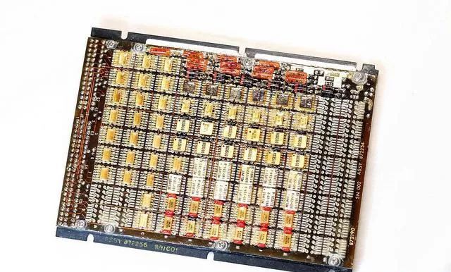 The flying wires are still unavoidable
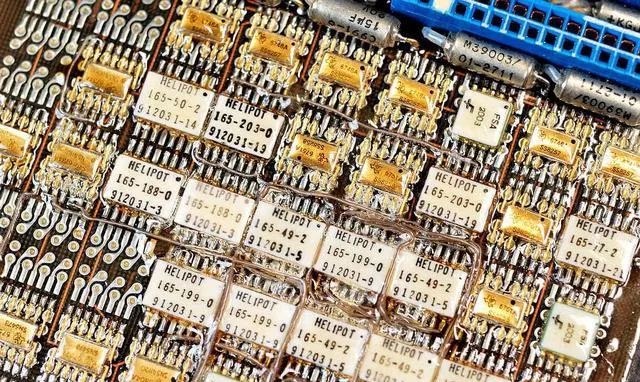 The two boards together, this is the back; they serve different functions and have different component layouts
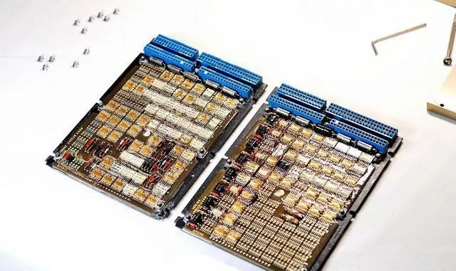 The front looks the same
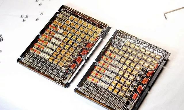 Let’s take a look at the serial number, one is 01, the other is 02. The serial numbers are printed on, the Americans really put in effort.。。
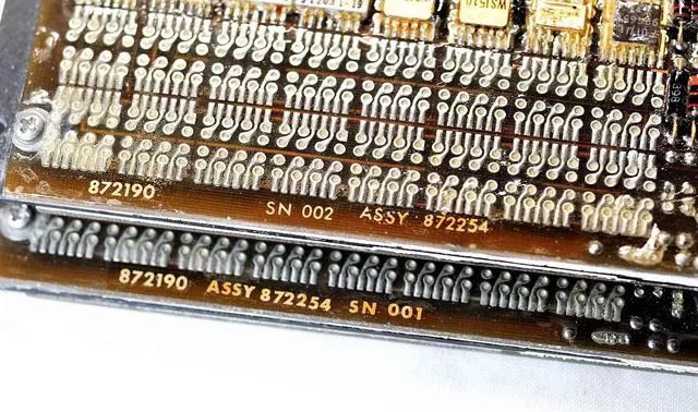 Close-up, modern 74HC chips and 50-year-old 54 chips appear together It is found that despite the passage of time, the pitch of the surface mount SO packaging has not changed at all in 50 years. One cannot help but admire the foresight of the Americans in setting standards. Looking at us, many standards are subject to constant changes, making it difficult to sustain.
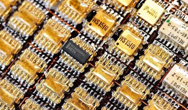 After removing the boards, the module is made of stainless steelwith gold-plated interfaces
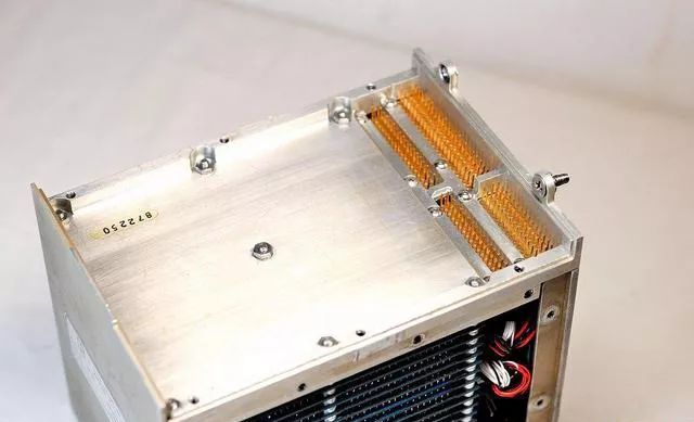 Further disassembly reveals the magnetic core storage The top is a diode board, and the ones below are the magnetic core boards. Unfortunately, they are soldered together, making it impossible to disassemble without damage, so I won’t disassemble them Diode array A bunch of wires
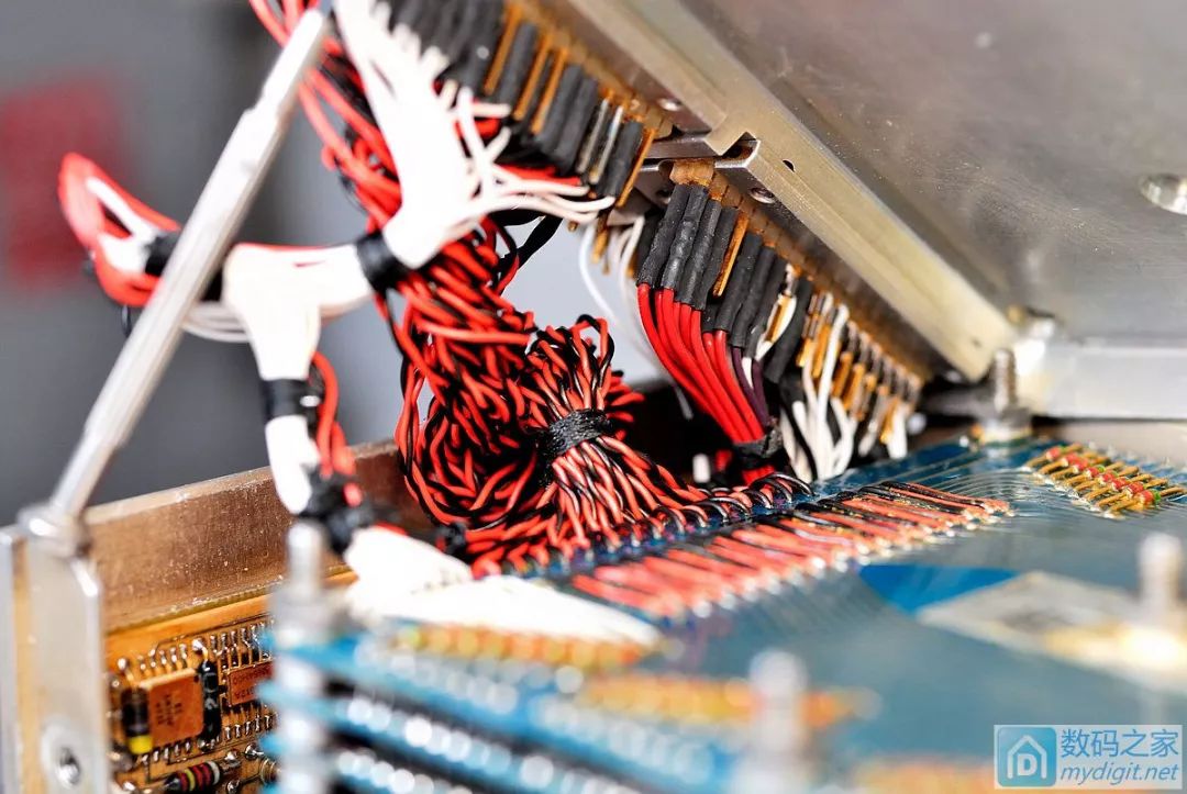 Here is a small board, and the chips on it are simply… From left to right, they are from National Semiconductor (NS), Texas Instruments (TI), Motorola, HELIPOT (a resistor manufacturer), and finally Fairchild.Finally, here are a few full views of the module. Because it is so beautiful, I couldn’t help but post a few more pictures
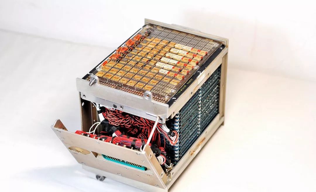
 Thus, the disassembly is completeFinally, here’s a picture that can serve as a desktop wallpaper
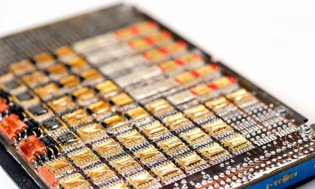
Finally, I recommend an amazing public account
Want to see more unique and cool products?
Want to know how to buy these fun things?
Want to easily avoid the big pits in buying?
Please follow "Mechanical Frontline", where 100,000 good products are waiting for you to discover
↓↓↓