Using a computer for industrial process control is relatively easy to achieve now. We already have microcomputers and specialized industrial computers (Industrial Computer), and many devices and instruments in industrial production processes have also been “digitized”. They even have their own “embedded computers” and SOC components. They can operate independently and connect with each other to form an Internet of Things type of process control system. This is the application of electronic computers in industrial automatic control.
However, fifty years ago, in the early 1970s, using computers for industrial process control was a new thing and a significant challenge. At that time, computers were very expensive, large, slow, had small storage capacities, and lacked human-computer interaction devices. How to solve the problem of automatic control of industrial processes? One needed a “computer” (digital type), and to connect the computer with production process control terminals (analog type) for bidirectional data exchange, to complete automatic processing and precise control according to industrial production processes and technological requirements.
The birth of the JKX-351 computer was centered around this purpose. At that time, the development of the computer and the connection with process control was the focus of the project. I was fortunate to participate in the entire process of developing this industrial control computer. From the end of 1974, for more than two years, the machine was successfully delivered to the production process control site, the system operated stably, and significantly improved product quality, having a major impact in the industry.
This project was a key engineering collaboration between the Computer Science Department of Chengdu University of Posts and Telecommunications and the Chengdu State-owned Guangming Equipment Factory (208 Factory, 35 Post Box), which produces special optical glass. The project’s goal was to use a computer to control the furnace temperature during the annealing process of optical glass products, by collecting temperature data through thermocouples mounted on the furnace body, converting it into digital signals, and sending it to the industrial control computer. The processed feedback signals would then be sent back to the production site to control the annealing temperature, forming a real-time closed-loop system.
Professor Liu Xinsong from Chengdu University of Posts and Telecommunications was the overall responsible person, with key participants including Professors Liu Shaoxian and Xiang Shiqing. I, along with classmates Yang Yinghua, Qi Renyi, and Li Shuguang, entered the project group as part of our graduation design. The technical department of the state-owned Guangming Equipment Factory also joined the project group, led by factory secretary Wang Zhihua and chief engineer Chen Nengqing, with technical leader Gu Shiwen (a Tsinghua graduate). Members included: Zhang Xiankang (Jiao Tong University), Jiang Weifu (Jiao Tong University), Tan Wanyou (South China Institute of Technology), Zhao Hengyou, Lin Youming, Zheng Qiming, Zhao Shicheng, Liu Yalie, and several assembly workers.
Upon first encountering the industrial control project, I initially felt completely clueless, so I began to “cram”. What to cram? I focused on the principles of computer arithmetic units, controllers, and memory that I had learned in class but had not truly understood. I also studied “industrial process control”, specifically the principles of PID automatic control: “Without direct human involvement, using external devices or apparatus (referred to as control devices or controllers), to make machines, equipment, or production processes (collectively referred to as controlled objects) automatically operate according to predetermined rules.”
My mentor, Professor Liu Xinsong, is a scholar with profound insights, rigorous academic standards, practical work ethics, strict management, and high academic attainments. During the project implementation, we were both teacher and student, as well as friends. His care, requirements, guidance, and encouragement benefited us immensely. This was the first project I participated in, and I later completed more than ten projects of various sizes. Professor Liu Xinsong’s rigorous academic approach, visionary outlook, and diligent work ethic have always motivated me and have been a guiding principle throughout my career.
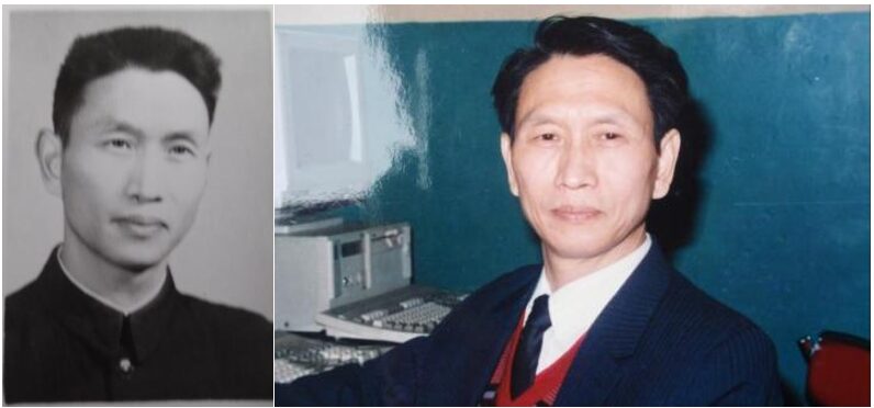
Professor Liu Xinsong
Author’s photo from that year
Special optical glass produced by 208 Factory often fluctuated between second and third-class products due to issues such as unstable furnace temperature control and annealing temperatures, resulting in a significant waste of materials and energy, and greatly impacting related industry applications. This type of special quartz glass, if imported from Germany, could not even be bought for one tael of gold. Out of a desire to bring glory to the country, the teachers from Chengdu University and the factory’s technicians undertook this honorable and arduous task.
At that time, there were no ready-made computers, so the task of developing an industrial control computer fell on the project group. The control computer was codenamed JKX-351, meaning “Computer Control System (35 Post Box) No. 1”.
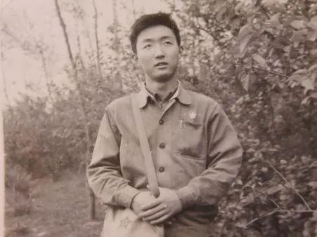
The entire system engineering included the development of the “industrial control computer” and the preparation for connecting it to the production process control (including instruments and meters). I still keep the complete set of notes, design records, and program coding books from the initial development process.
Author’s preserved design notebook, instruction design, and program coding book for the 351 machine
The industrial control computer has both the performance requirements of a general-purpose computer and the special requirements of a dedicated computer. First, it must be stable and reliable; secondly, it must still be stable and reliable, meaning the “mean time between failures” must meet certain requirements. It must not make errors during operation and cannot “crash” during production processes, which could lead to serious accidents.
At that time, the term CPU did not exist; the operation of the computer system relied on the arithmetic unit, storage unit, and control unit, which needed to be organically combined.
All three parts needed to be designed and assembled by ourselves, and each part was further decomposed into several independent boards interconnected by wires, which were then connected to external control devices (referred to as external devices) through interface devices (components). To keep it simple and reliable, the 351 machine did not design a full adder, but instead used two register groups, B and C, plus a carry chain to form the arithmetic circuit.
The word length was designed to be 16 bits (2 bits dedicated), with fixed-point representation as follows:
2-13< x ≤ 1- 2-13 or: 10-4< x ≤ 1- 10-4
Data and instructions were stored in original code format in memory (core memory). Instructions and data fetched from memory were retained in the C register in original code format. The C register was the only component that directly exchanged data with memory and also served as a regeneration register.
Instruction design adopted a micro-instruction format, encoding a total of 77 micro-operations. The instruction length was 14 bits, arranged together with data, determined by operation code. Program design and coding were recorded in octal code and punched into paper tape. The system frequency of the 351 machine was 125Kc, so each phase was 8μs (1/125).
A “real-time clock” was used to control the entire production process, with strict requirements on the execution time of each instruction, the execution time of instruction combinations, as well as the pulse delay, shaping, and level stability (temporary storage) time. During the later system debugging, we continuously calculated and adjusted the execution times (timing points) precisely, choosing the shortest instruction execution cycles. For example, instead of using an addition instruction for the “add 1” operation, we replaced it with the “exclusive OR” or “logical addition” instructions.
My main task was the design, modification, and debugging of the controller circuit and micro-instruction decoder circuit. As is well known, the instructions and their decoding lines are the most important parts of the core of modern CPUs. The length of the instruction code, the number of bits in the operation code, the types of address and control codes, and whether they are “indexed” or “relocated”, all needed to be studied and discussed word by word. Once the instructions were determined, their micro-operation potentials and pulses had to be set, and the decoding line design had to be conducted, which was our challenge. The potential or pulse output after decoding each instruction must connect with the corresponding circuit components; these interface components include data gates and carry chains of the arithmetic unit (accumulator), ports of registers, and decoding arrays of memory. One must be familiar with the timing of the entire system’s operation to understand when, where, and with what polarity (positive or negative pulse) the potential or pulse generated after instruction decoding should arrive at the next position, and the time limit for this.
Using discrete transistors to form logic and timing circuits, a very important and impactful issue was “gate delay”. The non-uniformity of devices and transmission delays could potentially affect and ruin the entire system. Every day we debated over the “NAND gate” structure, “inverter” structure, level and pulse polarity, gate cascading, control of gating pulses, and timing issues on the circuit diagrams. Furthermore, how long each instruction execution would take, and how long the execution time of combined instructions would be. Could some instructions be replaced with others to achieve the same result? Where to use “public operations” and “null instructions”, etc.
At that time, the circuit diagrams and PCB layouts were all hand-drawn, using drawing boards, pens, T-squares, and straight rulers, and then “exposed” to create blueprints. The code bus of the 351 machine was 14 bits, and a circuit board of about 200×100mm could only accommodate a meager two flip-flops plus additional circuits. Thus, the register group and carry chain circuits required seven circuit boards!
The computer cabinet was a tall iron frame, with plugin board slots evenly arranged on the frame. Each slot had a double-row socket, and the plugin boards contained discrete component registers (bistable flip-flops), cascading circuits, and control circuits. Looking from the back of the cabinet, the wiring was dazzling; these signal lines, data lines, and power lines had to pass through the gaps in the rack according to their start and end points. The gaps between racks were limited, with wire diameters of 0.2, 0.5-1mm. Many factors had to be considered in wiring, such as the shortest path, the best relay point, and the most reliable soldering point. Interference between wires also had to be considered, including the twisting density of twisted pairs, the use of unshielded versus shielded wires, and the isolation and shielding of pulse lines, level lines, and power lines, as well as grounding points and shielding points of the rack, and the interfaces and access points for external devices (long lines). Sometimes, we racked our brains over the routing of a single wire, changing wires repeatedly to eliminate interference.
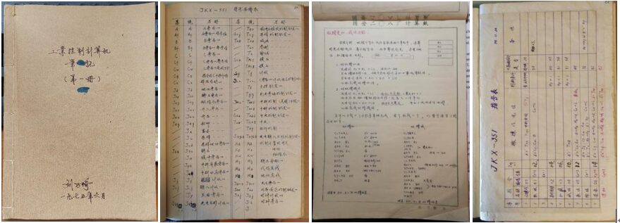
The layout of bistable circuits on the plugin board, the selection, testing, and pairing of transistors, and the screening of resistors and capacitors had to be done meticulously. To ensure reliability, even though they were expensive, we chose special-purpose components whenever possible.
The arithmetic unit and controller were finally successfully completed and connected to the core memory board, allowing normal operation. The level and pulse generated by micro-instructions and address decoding worked normally, and the timing from startup to data display was also normal.
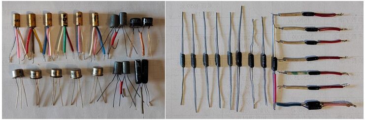
Transistors used at that time: 3AK, 3DK J series; diodes: 2AK series
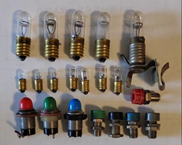
Neon lamps used for display
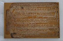
PCB plugin board
The control part of the 351 machine is equivalent to the CPU, and the memory uses core storage. So, how are instructions and data stored in memory and introduced into the control components for computation?
At that time, there were no “keyboards” or “displays” for computers. How to transmit data? How to achieve human-computer interaction? How to control the startup and termination of the computer? How to understand the operational status of the system? And how to switch to manual operation in emergencies? These were accomplished through a device called the “console”.
The console panel was equipped with a system power switch (button), data input buttons, and neon display tubes for showing the status of the B and C arithmetic units (data and address), memory status (breakpoints), and control point status (arranged by digit). It also had single, double, and triple position toggle switches for manually setting input addresses and reading addresses.
This manual operation mode had significant drawbacks, so it became urgent to configure the computer with a “display” and “keyboard”.
The display neon lamps of the 351 machine were installed on both the rack and the console, showing data changes and system control status respectively. The brightness of the neon lamps would fluctuate and flicker due to prolonged working hours and leakage current from the driving transistors, causing misjudgment of system control and data. Professor Liu Shaoxian was responsible for the display system, console, etc., and put a lot of effort into hardware reliability and spent considerable time on the design of neon lamp control and stability.
At that time, data input for the 351 machine had to rely on toggle switches and punched paper tape. The former was used on the console to set addresses and several key micro-instruction codes (similar to the DJS-130 machine’s manual setting of 13 codes), inputting them one by one to set the initial state of the registers and make the computer execute the initial instructions. The latter involved sending data-coded punched paper tape into the computer’s memory (core memory) through a tape reader for longer instruction sequences (programs). However, the data input via punched paper tape sometimes had to be sent multiple times to ensure the program’s completeness and correctness. Fortunately, the core memory had non-volatile characteristics, so the main control program remained stored in core memory after input.
At that time, the input method could not achieve real-time human-computer interaction, and the data sent into the machine could not be immediately confirmed as correct. To improve input speed and real-time capability, Professor Liu Xinsong boldly proposed using a teleprinter as the input and output device for the JKX351 machine, and I was assigned this task.
The teleprinter used a standard English keyboard layout. Unlike a typewriter, pressing a letter key would drive an electromagnet, which would print the letter on the teleprinter’s paper roll through a connecting rod. Important was that simultaneously pressing a key would generate a pulse sequence at the electromagnet’s connection port, with each letter key corresponding to a different code, known as teleprinter code. My task was to configure this device, which could serve both as data input and output, thus becoming a rudimentary “keyboard” for the computer.
The teleprinter was a model RFT-T51 from East Germany, fully named a teleprinter. Previously, I knew nothing about teleprinters and had no concept of how to connect it to a computer.
Within a week, I translated the user manual for the T51 teleprinter, analyzing the five-unit code sequence (international standard code table) for all keys and control keys of the machine. Based on task requirements, I listed the functions and timing: using the teleprinter’s keyboard to send key code information to the mainframe, which would receive the teleprinter code, translate it into binary code, store it in memory, and simultaneously print it out, controlling whether it would be punched into a five-unit paper tape.
The T51 input/output data was a double word length of 28 bits, using a 5-bit binary code to represent a decimal number. I then began designing the I/O control circuit, drawing the circuit block diagram, simplifying the logic merging of the 5-unit teleprinter code combinations, and designing the 28-bit printing register group, pulse source, and shifting circuit. Next, I designed the level conversion circuit (the mainframe used negative logic 0 to -12V, while the teleprinter used positive logic 0 to +10V) and the driving circuit for the electromagnet coil, using transistors (germanium and silicon tubes), selecting paired trigger tubes, writing data transmission and printing debugging programs, and punching the paper tape…
After several failures and improvements, I resolved level conversion, pulse width and delay, current and voltage stabilization, as well as power decoupling and filtering, finally achieving successful configuration. The teleprinter became a new tool for human-computer interaction, and also our first DIY “keyboard”, laying the foundation for command sending and data return for the 351 machine’s console, suitable for system debugging.
We also wrote a small program to control the teleprinter to print Chinese characters on paper and display them on the small screen of an oscilloscope.
The successful configuration of input/output (teleprinter) significantly shortened the system debugging time, enhanced real-time observation, and improved fault tracing and data analysis efficiency (with printing output capability).
Provincial and municipal leaders also visited the 208 Factory to observe the entire process of the innovative computer control system controlling production process parameters.
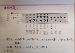
Five-unit punched paper tape
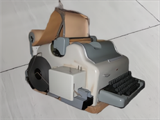
T51 teleprinter (with punched paper tape)
What is the relationship between the computer, “rain”, and “singing”? Why let the computer “rain” and “sing”?
The core memory of the JKX-351 computer is the main memory of the transistor industrial control computer, with a capacity of 2048 bits (later expanded to 4096 bits), divided into 8 pages (boards), each page containing 256 units, controlled by a four-bit page register to access the core memory pages. The storage bit still consists of 14 bits plus one parity bit (15 bits). Given the low operating speed of this machine, a line-based approach was used to implement “tower decoding” and “parity checking”.
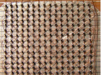
Professor Xiang Shiqing was responsible for the design of the computer’s memory. Hundreds of thousands of small magnetic rings with diameters of about 0.4-0.5mm were arranged in an M×N array, with insulated wires thinner than hair passing through three or four rings in a specific order to form a memory plane. If pulse currents were applied to the output lines, the direction of the current could flip the magnetization of the cores, thus forming data records, with each small magnetic ring serving as a data bit (one bit).
To check the stability of the core board and memory, read/write tests had to be conducted. Among many memory testing schemes, “rain” was a special checking method. It involved cyclically writing data patterns with certain rules into the core memory matrix and then reading them out for comparison, verifying whether the “read/write” was normal, testing the magnetization flipping effect of the core, and the quality of the read/write circuits and driving circuits. This test is known as “dynamic light point detection”, also referred to as “rain” inspection.
If during the reading and writing of these cyclic codes, the flowing or induced electrical pulses on the read/write driving lines were sent into the audio circuit, the different distributions of data bits would produce different sound frequencies, creating a “ding ding dong” sound resembling raindrops in the speaker. If these signals were connected to an oscilloscope, a series of light point patterns would appear on that small green screen, moving downward with the sound of the “ding dong”, truly resembling “rain”. Those who witnessed and heard this “rain” scene and sound felt it was a beautiful metaphor and a delightful sound!
The “rain” inspection is a very strict test for the core memory, commonly used to determine whether the memory system is working normally, serving as a “machine test” process. This “machine test” often needs to be continuous, lasting 24 hours, 48 hours, or even longer. This test also determines the “mean time between failures” of the entire computer system, serving as a standard for evaluating computer performance.
Whenever it “rains”, we all hope that this “rain” sound can be continuous and clear, indicating that the memory is undergoing strict read/write testing. If the memory is unstable or faulty, the “rain” sound will be chaotic and unclear, and the patterns on the oscilloscope screen will be messy. When the “ding dong” sound suddenly stops, we often feel a sense of regret, “Oh, it stopped raining?!” Especially when the “rain” is intermittent, it can be quite distressing, so several of us would lie on the floor again, leaning against the rack, repeatedly measuring pulse waveforms and adjusting pulse timing until that rain sound could continue for a few hours, tens of hours, or even days. Only then could we computer enthusiasts sleep soundly on the floor of the machine room, accompanied by the sound of rain. Older computer workers who were familiar with this “rain” sound dedicated their youth quietly yet fervently to this noble cause.
“Singing” is another method for checking whether the core memory system is functioning normally. It involves using the computer to read data from the cores or execute programs in memory, employing counting, looping, and output program techniques to compile a “singing program”. The program’s punched paper tape would be input into memory via a photoelectric input machine, and then the program would be started. Thus, a beautiful melody would be played through the speaker.
Of course, this process is very time-consuming and mentally taxing. It requires considering the correspondence of sound frequencies, high and low pitches, and rhythms to determine the number of program loops. Then, according to the machine code of the program, this program code would be punched into paper tape, and the photoelectric input machine would read the punched code to input the music tape program. Based on the pitch and sound quality of the “singing” (playing music), the program code would be continuously adjusted until it sounded satisfactory. Naturally, the first song played by the computer was “The East is Red”. Master Zhao Hengyou also compiled a performance program for “Little Bamboo Raft Drifting on the River”.
In an era without keyboards and displays, this was a very difficult yet very cool job. It often involved repeated adjustments, constantly modifying and patching punched paper tapes, and even completely re-punching the entire program. At that time, Master Zhao Hengyou from the 208 Factory project group worked day and night to compile testing programs such as “Memory 0-1 Interference” and “Worst Layout Check”, while Chengdu University colleagues Qi Renyi, Li Shuguang, and Yang Yinghua made significant contributions to the “Performance Program” and “Character Display”.
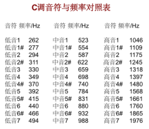
Table of notes for notes and frequencies
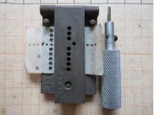
Punched tape patching machine used back then
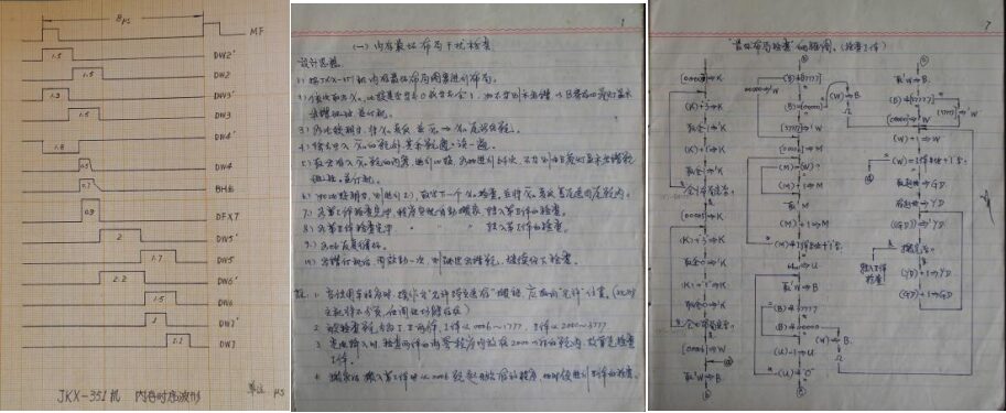
Notes on JKX-351 memory timing waveforms, interference checks, and worst layout checks
After the basic configuration of the JKX-351 computer system was successfully completed, it had to be connected to the production process site for system debugging to verify the operational status and stability of the computer, as well as to observe and validate the actual effects of the computer on controlling the furnace temperatures of more than a dozen furnaces. This was a “system engineering” task, not just about passing the computer debugging; at this point, “engineering thinking” was presented before everyone.
Production process control is a “system engineering” task, which not only needs to solve the stability issues of the computer but also the stability issues of external devices and peripheral devices (instruments and meters) connected to the computer. It must address not only the “hardware” issues but also consider the “software” issues. Moreover, it must take into account the working environment of the computer itself. This is an “engineering problem”. It can make over a hundred combinations, forming tens of thousands of parameter data, autonomously selecting and compiling annealing process curves, and automatically controlling operations, further unleashing the capabilities of the control system. This was also the most complex and difficult problem I encountered during the development process, which I would like to share with everyone.
Initially, to gain experience and learn lessons, Professor Liu Xinsong organized several groups to visit various enterprises across the country that were engaged in industrial production control to learn from their computer-controlled production processes and understand the issues they encountered, as well as their experiences and lessons.
My group visited: Lanzhou Refinery (which used the Japanese HOC-510 computer to control the contents of wind, oxygen, ammonia, sulfur, and the process in the catalytic tower); a factory in Houma, Shanxi (which collaborated with Taiyuan Institute of Technology to use a computer for military product production control); Shenyang Computer Technology Research Institute (which used the PDP-11 minicomputer for data processing); and Anshan Steel Company (which used the K351 computer to control the annealing furnace).
The results of our research provided us with insights: the reliability of the computer itself, the stability of the power supply, the stability of the program, and the stability of the “long lines”. Many of these were engineering problems, thus “engineering thinking” was presented before us.
In the process of developing this project, computer development was a key focus, considering aspects such as computation, control, storage, data transmission, and interface adaptation (unlike now when computers are directly purchased for use). Another key focus was the monitoring of production processes and data processing, including system control programs (at that time, the concept of software did not exist).
Professor Liu Xinsong, with a high-level perspective, oversaw the overall situation from the perspective of control processes and system engineering. The factory project team, under the leadership of senior engineer Gu Shiwen, worked tirelessly in high temperatures for furnace temperature detection control, instrument management, and process monitoring, actively cooperating with the implementation of the control system.
The success of an industrial control computer system is related to the objects it monitors and controls, and to the entire production process. The reliability of the machine is the foundation of the stability of the control system, while the power supply, machine room environment, peripheral devices, and the signal transmission lines (referred to as “long lines”) between the instruments and meters controlling the production site are also extremely important for reliability.
The power configuration of the 351 machine was complex. Due to different basic power supplies for devices, components, and parts, the core memory (including drivers) had +6v, ±12v, -24v; the control part had +6v, -12v, ±45v (DCT); and the display part had +20v (for neon lamps), etc. The logical levels of each device had to be converted, which could become potential “fault points”. The power system had to stabilize voltage and frequency, filter decoupling, and provide power-off protection. To avoid interference from mains fluctuations, a 220v/400Hz generator was used, rectified and stabilized for computer operation.
The design of the conversion and transmission of switching signals and analog signals was an important task for the project team. To handle emergencies, the computer system was configured with “interrupt systems”, “real-time clocks”, “breakpoint restarts”, “alarm systems”, and “human-machine switching” hardware (boards), and programs (paper tape punched program codes) were compiled to implement these functions.
The wiring of the computer cabinet and the connections between various boards and sockets used soft plastic wires of 0.2, 0.5, and 1mm, with some using 1mm metal shielded wires and twisted pairs. Preventing cold solder joints and selecting the density of twisted pairs to combat interference greatly affected transmission reliability, which was also a guarantee for the successful implementation of the engineering project.
All functional boards of the JKX-351 computer were pluggable, with connection wires soldered from plugs behind the sockets and connected to another socket or rack. At this time, the soldering, routing, passing through racks, bundling, and color coding of wires (for easy distinction), as well as the isolation between signal wires and power lines became research issues. As a process standard was issued, workers responsible for assembly were required to follow it.
Another issue was the “long line” problem. From the workshop site to the computer control room, the signal transmission distance and time were lengthy. “Long line transmission” had to ensure the quality of the signals (stability, attenuation, distortion, time delay, interference, etc.), and also consider the time delay of control signals reaching execution devices, as well as the inertia of the execution devices. The choice and anti-interference treatment of “long lines” (shielded and unshielded wires), the design and planning of the grounding system (grounding points, whether to use floating ground, single-ended or double-ended grounding, etc.), and the laying and safety of external “long lines” (such as through pipes, on the ground, overhead, anti-lightning, waterproofing, rodent-proofing, etc.) were no longer merely issues of the computer system itself.
At that time, there was no concept of “software”; there were only codes and programs. Given the small capacity of core memory, although it was non-volatile storage, it could only store core system codes. All system programs (such as system debugging, memory testing, etc.), control programs (PID control, process curve simulation, etc.) had to be pre-compiled into codes and preserved on punched paper tape for future input. This was also a significant challenge for us. I still keep the punched paper tapes of program codes from that time.
Once in the production process, the computer was not allowed to stop; it continuously ran core control programs, dynamically detecting signals from the production site, matching the optimal process curves, and making dynamic adjustments and controls. To ensure signal timing, level stability, and the “inertia” delay of control terminals, the instruction selection in program compilation required considerable thought.
This series of work expanded our “computational thinking” to “engineering thinking”, gaining knowledge that could not be obtained from books, which was also one of the prerequisites for computer applications, benefiting me immensely in various projects I undertook later.
The system debugging was the final sprint phase, with the computer project team, teachers, technicians, and workshop workers working day and night together. The optical glass firing and annealing cycles took several days, requiring stable process parameters.
After several rounds of repeated debugging and corrections, the 351 computer passed the test, enabling the company to produce high-quality products for the first time, achieving 98% first-class products and eliminating second-class products!
The development and successful application of the 351 computer control system had a tremendous impact in the industry. At that time, the national standard for the average mean time between failures for machines was 50 hours, but the 351 machine astonishingly reached 1000 hours (over a month). The reputation of Chengdu University of Posts and Telecommunications in computer control specialties soared domestically, paving a unique path for Chengdu University. Provincial and municipal leaders visited the factory to observe the computer-controlled production process, and related enterprises and schools from across the country came to visit and learn. This project won the first prize from the Ministry of Machinery Industry, the second prize from the Ministry of Electronics, and the Science Conference Award from Sichuan Province in 1978.
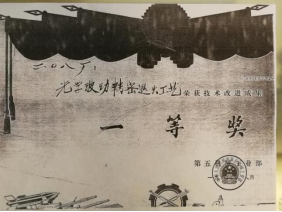
First Prize from the Ministry of Machinery in 1980
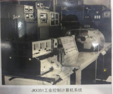
JKX-351 Industrial Control Computer System
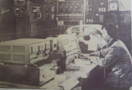
Professor Xiang Shiqing operating the console

Factory leaders inspecting the system
Front row from left to right: Chen Yuanzheng (Chief Engineer), He Changhui (Factory Director), Zhang Xiankang, Liu Xinsong
Back row from left to right: Gu Shiwen, Xiang Shiqing, Dang Liping, Lin Youming, Zhang Renzhong
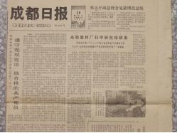
Report in Chengdu Daily on March 26, 1980
From 1974 to 1978, the single furnace temperature control experiment was successful; from 1978 to 1979, a multi-furnace temperature control experiment was also successful. Since June 1979, after identification and acceptance by the competent department and more than a dozen relevant research institutes and universities, it has been put into trial production and has been operating normally. The yield of products produced has increased from an average of 50% to over 90%, and the annealing effectiveness has also increased by about twice.
The successful development of the JKX-351 industrial control computer system is the result of joint efforts between universities and enterprises, with everyone contributing and striving hard. In an era when there were no “CPU” chips, integrated circuits, precision processing equipment, or precision measuring instruments, completely relying on “discrete components”, plug-in boards, manual soldering and wiring, and ordinary oscilloscopes for debugging, the assembly of an industrial control computer system was indeed a groundbreaking achievement.
Based on this project, the factory later used microcomputers for furnace temperature control and annealing processes under the leadership of Gu Shiwen. By the late 1980s, the performance of microcomputers far surpassed that of the JKX-351 machine, but that is another story.
With the development of computer technology, microcomputers, single-board computers, and microcontrollers emerged successively. Memory progressed from core memory to semiconductor memory, with computing power and storage capacity rapidly advancing, promoting the popularization and promotion of computer applications. The emergence of SOC has further embedded computers into instruments and equipment, laying the foundation for the current era of the “Internet of Things”.
Chengdu University of Posts and Telecommunications, besides the responsible Professor Liu Xinsong, had other members including: Liu Shaoxian, Xiang Shiqing, Liu Naiqi, Yang Yinghua, Qi Renyi, Li Shuguang (Class 7221). Dang Liping, Zhang Shurong, Tong Ling, Wang Tianren (Class 7312). The state-owned Guangming Equipment Factory (208 Factory, 35 Post Box) included Wang Zhihua (Secretary), Chen Nengqing (Chief Engineer), leader Gu Shiwen, and members Zhang Xiankang (Jiao Tong University), Jiang Weifu (Jiao Tong University), Tan Wanyou (South China Institute of Technology), Zhao Hengyou, Lin Youming, Zheng Qiming, Zhao Shicheng, Liu Yalie, and many assembly workers who also participated in this work.
On March 26, 1980, Chengdu Daily published a special report on this project: The Guangming Equipment Factory reaped the fruits of scientific research, and the JKX-351 type electronic computer developed successfully has been used in production, opening a new path for new technology in optical glass production in China.
Time flies, and things change. Reflecting on the entire DIY computer process from yesterday and comparing it to the DIY computer process decades later is truly a world apart. My understanding of Chengdu University has deepened: the intelligence, diligence, and perseverance of Chengdu University people, their spirit of self-reliance, innovation, and creation is a valuable asset of Chengdu University. They are undoubtedly the pioneers in China’s electronic information technology field!This project is also the crystallization of school-enterprise cooperation, combining “computational thinking” and “engineering thinking”.
Finally, I would like to conclude this article with a small poem I wrote at that time:
“Fighting for the 351”
Staying up all night, fighting for the 351;
All groups busy, system debugging in unison;
Focusing on pulse measurements, kneeling to test signals;
Switching between digital and analog, long lines to prevent interference;
Strong tea to drive away fatigue, cold water to refresh the mind;
Neon lamps flickering, as if the machine is smiling;
The sound of rain in memory, lulling me into a brief sleep;
The clear sound of the teleprinter, sending good reports;
The furnace’s flames are red, the crystal glass is beautiful;
Another achievement to celebrate, Guangming stands out!