↑ Click on the top “Chinese Society of Surveying and Mapping“
to quickly follow us
Abstract:
Automated Guided Vehicles (AGVs) have various methods for indoor positioning, with LiDAR matching being one of the main techniques. However, in areas with few environmental features, the lack of constraints can lead to matching errors. To address this issue, this paper proposes a combined navigation method using LiDAR and QR code landmarks, and simulations were conducted using a TurtleBot3 in an indoor corridor environment. The results show that the average error of pure laser matching navigation is 11.5 cm, while the combined navigation method with QR codes can control the average error within 2 cm. This method enables precise positioning and navigation of AGVs in environments with limited features, enhancing their adaptability and reliability in the working environment.
Keywords: LiDAR; QR Code; Indoor Positioning; Automated Guided Vehicle; Navigation;
Read the full text:
http://tb.sinomaps.com/article/2021/0494-0911/20210102.htm
Today, the high intelligence and simple operation of automated guided vehicles (AGVs) provide a fast, efficient, and convenient transportation method for indoor scenarios such as warehouses. Positioning and navigation accuracy has always been a key focus and challenge in indoor AGV research, where laser and camera sensors are widely used in indoor positioning. At the same time, inertial navigation, ultra-wideband technology, magnetic navigation, and various combined navigation techniques also play important roles in indoor positioning.
For robots equipped with LiDAR, Adaptive Monte Carlo Localization (AMCL) is a commonly used positioning method based on particle filtering, which can adapt to most indoor environments. However, in environments with insufficient feature points and similar map scenes, its positioning reliability is poor, leading to deviations from the preset path. QR codes can store a large amount of useful information, such as coordinates, and their three positioning corners can provide a reference for the robot’s current posture. They are easy to deploy, low-cost, and highly flexible, making them a good means for indoor auxiliary positioning.
In light of the above, this paper addresses the issue of insufficient feature points in indoor positioning by using LiDAR matching positioning while correcting positioning coordinates through camera recognition of QR code landmarks, and it conducts on-site testing in corridors to demonstrate the accuracy and reliability of this method.
Under LiDAR matching positioning, the QR code coordinate correction algorithm should first establish an environmental grid map. At the start of navigation, the robot’s initial pose in the grid map is determined, and N initial poses are copied as the initial particle group for AMCL. During operation, the particle group adjusts its position based on the robot’s movement, calculating the matching degree between the current frame of LiDAR and the occupied grid. Each laser point has a corresponding evaluation score based on its matching situation with the grid map. When a laser point coincides with an occupied grid, it receives the highest score. Ultimately, the robot’s pose information is described using a Gaussian distribution, and the motion path based on positioning and target planning is sent to the lower computer to control the servo movement. During movement, when the camera scans the QR code, the calculated QR code coordinates are fed back to the positioning algorithm, using these coordinates as the new initial coordinates to redistribute the particle group, forming a feedback control loop.
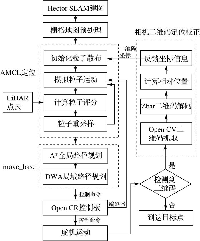
Figure 1 Algorithm Process
SLAM (Simultaneous Localization and Mapping) refers to obtaining the robot’s real-time pose in an unknown environment and creating an environmental map. In this paper, the mapping phase adopts the commonly used Hector SLAM method in laser SLAM.
Adaptive Monte Carlo Localization (AMCL) is a probability-based localization method based on particle filtering. Particles are uniformly distributed around the initial position, and the robot’s motion model is used to estimate the positions of the particles. At the same time, the points returned by the laser are matched with the map, scoring the credibility of each particle position, retaining high-scoring particles as the robot’s pose while discarding low-scoring ones and adding new particles to maintain the cycle.
To simulate particle movement, it is necessary to understand the robot’s motion model. The differential drive mainly controls steering and curved motion through the speed difference between two wheels. The direction of rotation and the radius of curved motion can be achieved by the rotational direction of the two wheels and the speed difference ΔV. The robot’s motion model can be represented as
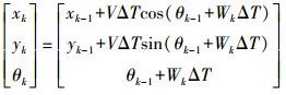 (1)
(1)
Click to view the formula
Where (xk, yk, θk) is the robot’s state at the current moment; (xk-1, yk-1, θk-1) is the robot’s state at the previous moment; V is the speed; W is the angular velocity.
In the ROS navigation node, the robot’s preset trajectory is segmented into equidistant discrete points. The robot is given an initial coordinate position, and based on the robot’s current pose, target position, and global grid map, the A* algorithm can plan the optimal global path to reach the next target point. The Dynamic Window Approach (DWA) constructs a local path based on this, enabling dynamic obstacle avoidance for the robot, converting the path into control information sent to the robot’s Open CR control board to drive the servo, allowing the robot to move along the trajectory. Meanwhile, servo operation data, the global map, and LiDAR data are fed back to the AMCL positioning algorithm for real-time estimation of the robot’s pose during motion, thus achieving closed-loop control of the robot.
The QR code stores the precise coordinates of that point. By calculating the relative position of the center of the image to the QR code in the current frame, the actual coordinate information of the robot can be obtained. As shown in Figure 2, the three boxes on the QR code serve as the three positioning markers, P0, P1, P2, and P3 are the four corners marked counter-clockwise, and θ is the angle between the QR code and the camera.
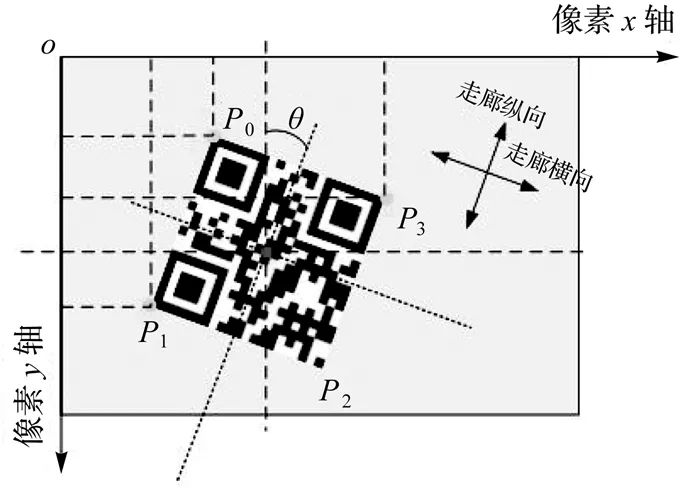
Figure 2 QR Code Recognition
When the QR code appears in the image, the camera’s coordinates are as shown in Figure 2, taking the center coordinate of the QR code as the correction point, the center pixel calculation formula is
 (2)
(2)
Click to view the formula
Where (xP, yP) are the pixel coordinates of the corners; (xcenter, ycenter) are the pixel coordinates of the center of the frame; (Δx, Δy) are the actual correction coordinates; k is the scaling factor.
The angle between the QR code and the camera frame is
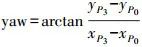 (3)
(3)
Click to view the formula
Since this angle is in the form of Euler angles, it needs to be converted into the quaternion form commonly used in robot control. This paper’s positioning and navigation only study the two-dimensional plane, so only the yaw angle is considered, with the pitch and roll angles both at 0°. The simplified Euler angle to quaternion formula is
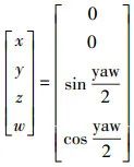 (4)
(4)
Click to view the formula
The obtained corrected pose is fed back to the AMCL, redistributing the particle cloud to achieve QR code positioning correction.
This experiment used the TurtleBot3 Burger model robot, equipped with a Raspberry Pi 4 development board, controlled and calculated data using a master-slave connection method. The relevant code and calculations for the experiment were run within the ROS operating system.
In terms of kinematics, the robot operates using a differential drive. In terms of sensors, it is equipped with a Hokuyo UTM-30LX-EW single-line LiDAR, and the camera uses the Raspberry Pi’s original V2 camera with a fixed focus of 8 million pixels.
The Hokuyo LiDAR and Raspberry Pi camera are connected to the TurtleBot3 robot, with the camera scanning the QR code landmarks vertically downward. In ROS, the coordinates of the robot’s various sensors are linked with the Base footprint reference coordinate system, clarifying the transformation parameters between the various coordinate systems.
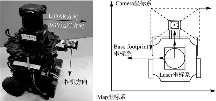
Figure 3 Experimental Robot
Using the Hector SLAM method, a two-dimensional grid map of the experimental environment was established, with a grid resolution of 1 cm. Since this paper studies navigation methods in low-feature environments, the features in the middle of the two-dimensional grid map were processed using Photoshop to remove some features, better simulating an open and narrow corridor environment. The final navigation feature map obtained is 10 m long and 1.92 m wide.
During navigation, the adaptive Monte Carlo localization of the LiDAR is used, and the A* global path planning algorithm is employed to run along a fixed path between points, using the dynamic window algorithm for local path planning to avoid obstacles. OpenCV is used to capture real-time images frame by frame, and the Zbar library extracts QR code information, using the coordinates carried by the QR code to unify the matching errors of the LiDAR and the operational errors of the robot’s servos. In the experiment, the scanning radius of the LiDAR is limited to 2 m. To ensure that the QR code is successfully recognized between the real-time image frames, the camera’s real-time image is set to 60 frames, with a frame size of 320×240 pixels, covering an area of approximately 20 cm×15 cm on the ground, and the robot moves at a speed of 0.11 m/s, with an allowable error of 3 cm when reaching the target point.

Figure 4 Experimental Scene and Navigation Map
The experiment adopts a fixed-point navigation mode, setting a polyline trajectory and establishing target points for the robot to advance along the trajectory in the corridor to reach predetermined target points. QR code markers are placed along the robot’s running trajectory, spaced 1 m apart, with each QR code accurately determining its relative coordinates in the grid map. As the robot runs along the predetermined trajectory, when it reaches above a landmark, the QR code is captured by the camera, allowing the current precise position and heading angle of the robot to be determined based on the position and offset angle of the QR code relative to the camera frame.
The experimental results recorded three sets of trajectory data: the running trajectory without external correction, the trajectory in the simulated low-feature environment with a radius of 2 m, and the trajectory with QR code correction under low-feature conditions. Meanwhile, nine specific points were selected along the robot’s running direction, measuring the absolute value of the error between the robot’s arrival at that point and the set coordinates, with each specific point spaced 1 m apart. The final accuracy data for heading and lateral positioning under laser positioning and QR code correction were analyzed to draw conclusions.
This experiment produced four sets of trajectory data, as shown in Figure 5.

Figure 5 Comparison of Robot Motion Trajectories
Due to the constraints of the walls on both sides of the robot’s position, the laser scanning features of the walls are prominent, so there will not be significant positional errors in the heading. The three trajectories are basically coincident on the y-axis of the map. In the corridor environment, the robot’s positioning deviation mainly manifests in the longitudinal direction of the corridor. The QR code-assisted navigation performs well, closely aligning with the actual trajectory. Pure laser navigation shows significant error in the mid-late stages, and without constraints, the error accumulates over time and displacement, making it unable to follow the set trajectory.
The accuracy on the x-axis and y-axis of the map is shown in Figure 6.
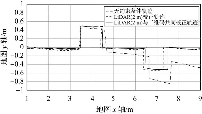
Figure 6 Comparison of Specific Point Navigation Errors
In terms of heading, the robot’s heading error shows a trend of first increasing and then decreasing. This is due to the initial position being at the door, where the map features are prominent, resulting in high matching positioning accuracy. As the robot runs to the middle of the corridor, the error gradually increases, with the middle section having only the wall features on both sides, increasing the likelihood of mismatching during the robot’s movement. The particle filtering performance also does not completely converge, showing a line-like rather than a precise positioning cluster state. After running 6 m, the maximum error can reach 20.0 cm. However, with the QR code positioning correction, the robot’s heading navigation accuracy is significantly improved, with a maximum error of 2.1 cm. The experimental results also show that the accuracy differences between the two methods on the y-axis of the map are minimal, with the maximum error of laser matching positioning being 2.5 cm and the maximum error after QR code correction being 1.5 cm.
The root mean square error was calculated for each point, resulting in Table 1. It can be seen that when combined with QR code navigation, the root mean square error is significantly reduced, and navigation accuracy is effectively improved.

Table 1 Comparison of Root Mean Square Errors
This paper describes the shortcomings of existing laser matching positioning in low-feature point environments and proposes a fusion positioning method based on QR code recognition and LiDAR matching. Finally, experiments demonstrate the feasibility of the new method. QR code recognition has its limitations, such as requirements for lighting and clean surfaces, but its advantages are also very evident, with low cost and convenient operation making its application scenarios very broad. The navigation accuracy when combined with QR codes in specific situations is quite remarkable and meets the operational requirements of AGVs.
END
Citation format: Zhou Zongkun, Jiang Weiping, Tang Jian, et al. LiDAR Mapping and QR Code Fusion for Indoor Positioning and Navigation of AGVs [J]. Surveying and Mapping Bulletin, 2021(1): 9-12, 52. DOI: 10.13474/j.cnki.11-2246.2021.0002.
Author’s introduction: Zhou Zongkun (1995-), male, master’s student, main research direction is LiDAR SLAM.
Editor: Zhang Yongchao
Initial review: Qi Yang
Review: Peng Zhenzhong