This article is dedicated to all the electronic fathers working away from home.
Introduction
Due to working in different locations, some ordinary tasks can become quite inconvenient. Here, I will discuss the challenge of tutoring children remotely.
In a typical household, an adult can simply pull up a chair next to the child, put on the mask of a strict father or a caring mother, and start tutoring. Although the process may not always be pleasant, at least it is tangible and direct. However, when you add the condition of being a thousand miles apart, things become a bit tricky.
The usual method available to you is video chatting via a smartphone. At this moment, you transform into an electronic father, with the camera acting as your eye. But this eye isn’t very effective; it can only focus on the child’s face. When the child points to a word in their homework and asks how to read it or points to a question and asks how to answer it, this wretched electronic eye cannot move, and you don’t have an electric neck to look down at the desk. You can only stare at each other before finally saying, ‘Get your mom.’ When she arrives, she will only give you a disdainful look, and you will have to sulk in a corner, forgotten, staring blankly at the white ceiling.
This situation greatly dampened my enthusiasm to be a good father, even if just an electronic one. As a technical person, I decided to tackle this issue with technology. First, let’s analyze: to be a competent electronic father, I need to ensure effective remote tutoring for my child, which may require several electronic components:
-
Two electronic eyes, one to watch the child and one to observe the homework. -
An electric neck that can turn up, down, left, and right.
After some market research, I found that there are a few commercial products that specifically address this need, but either the prices are exorbitant or there are some unsatisfactory aspects. Thus, embracing the spirit of a geek, I decided to create my own solution.
This task isn’t complicated; first, the requirements are clear. We need to establish a simple and efficient technical solution: considering costs, we will continue to use video chatting, utilizing the iPad’s camera as one of the eyes to primarily see the person and talk. On this basis, we will prepare a Raspberry Pi as an auxiliary device, adding a high-definition camera with auto-focus to clearly see the words on the homework at any time, and adding a gimbal underneath it to allow for up, down, left, and right movement. Finally, we need a reliable network with low latency, and thus, a perfect remote electronic father is born.
The general plan is sufficient to meet the current needs. Let’s get started, beginning with hardware, by directly purchasing the following components online:
-
Raspberry Pi 4B motherboard with 4GB RAM (373 RMB). -
Raspberry Pi Camera Module 3, 1200W pixels, auto-focus (199 RMB). -
Raspberry Pi 4B/3B+ two-axis gimbal expansion board (102 RMB). -
Overhead smartphone holder (87 RMB).
After solving the hardware issues, we will tackle the software problems:
-
Install the latest <span>Raspberry Pi OS</span>system on the Raspberry Pi. -
Use <span>libcamera</span>to capture real-time image data from the camera. -
Use <span>ffmpeg</span>to encode the camera’s image data into<span>h264</span>video streams. -
Use <span>UDP</span>hole punching to establish a<span>P2P</span>direct connection, sending images in real-time to the other end. -
The other end receives the video stream, decodes it, and uses <span>SDL2</span>for real-time preview playback locally. -
On top of the video stream, establish a control stream to control the gimbal’s servo direction.
In the following articles, I will share the complete implementation methods and steps of this technical solution, guiding each remote electronic father step by step to DIY a complete remote tutoring system for their children.
Hardware Assembly
First, after obtaining the Raspberry Pi, we download the image burning tool from its official website, <span>Raspberry Pi Imager</span>, select Raspberry PI 4 and Raspberry PI OS (64-BIT), insert the sdcard, configure the WIFI account and password, and then download and burn the system. Finally, power on the Raspberry Pi and ensure that <span>ssh</span> can be accessed.
The next step is to install the camera and gimbal, which can be done according to the instructions provided by the seller. The final installation effect is approximately as follows:
Then, place the Raspberry Pi with the installed gimbal and camera onto the overhead smartphone holder, completing the overall hardware assembly. The final assembled effect is as follows:
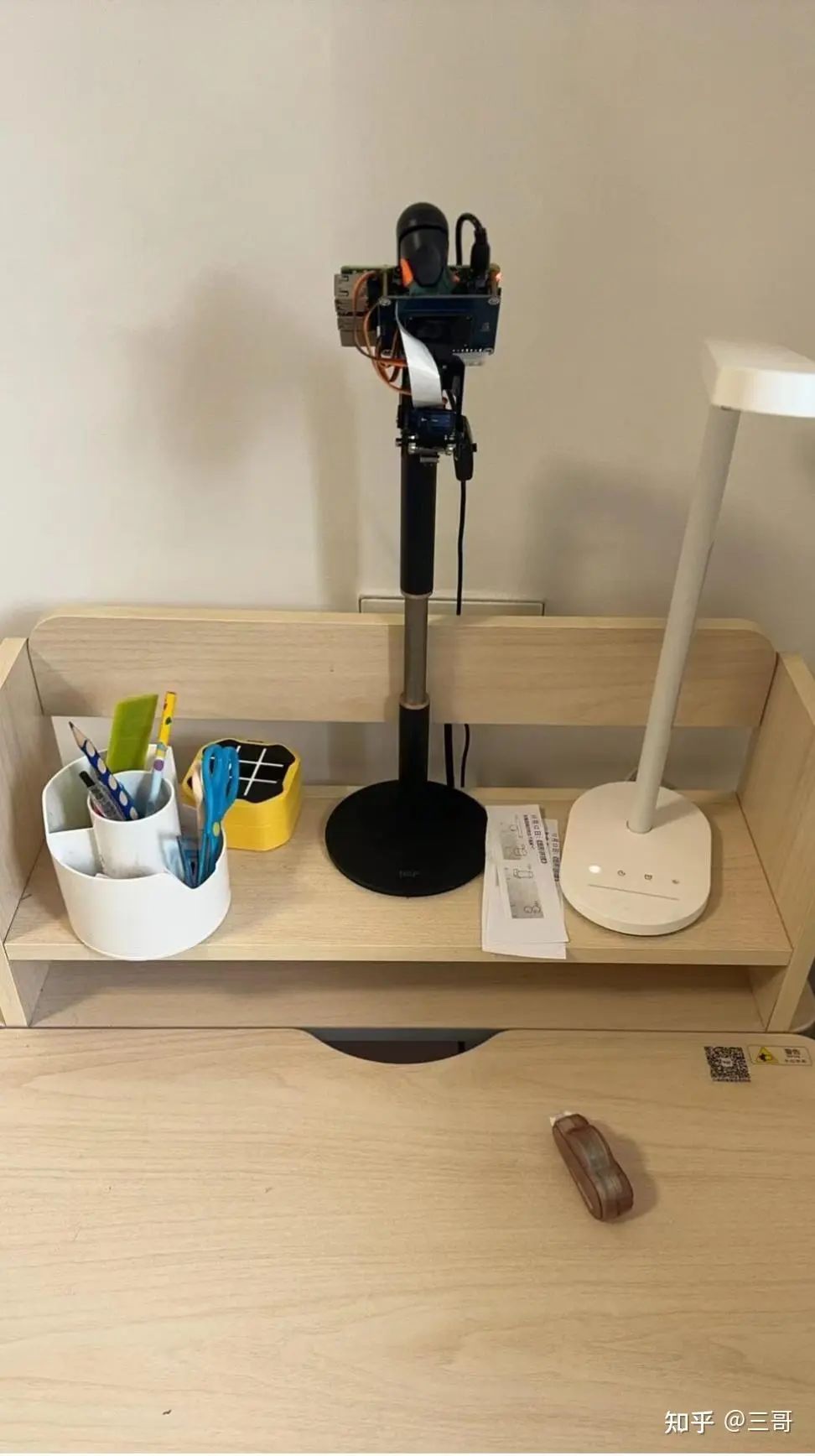
Thus, an electronic father is basically assembled. It primarily acts as our neck and one eye, as this is a 4K high-definition camera that supports fast focusing, and with the gimbal, it supports rotation in two dimensions, up and down, left and right. This allows us to see almost all the words on the textbooks and homework on the desk, making tutoring much more convenient.
In front of it, we also need to place an upright iPad on the front of the desk, along with various video chatting communication software (for example, I recommend using Tencent Video, which offers free 1v1 calls without time limits and includes an electronic whiteboard), mainly to act as our other eye, monitoring the child’s various small movements and allowing them to see our face for authority.
Software Development
After assembling the hardware, the next step is software development. Essentially, we need to develop a real-time streaming media system based on P2P. There are two ends: one end is the Raspberry Pi, which mainly collects the camera image in real-time and transmits it to the other end. The other end is a client on a computer or mobile phone, which only needs to receive the data, decode it, and display it, plus a control stream to rotate the camera gimbal.
I have developed two versions: first, both ends use <span>python</span> to quickly develop a minimal runnable demo to verify the feasibility of the entire technical plan. After ensuring that the plan has no major issues, I switched to using <span>C++</span> to formally develop this project, which includes two programs supporting <span>Raspberry Pi OS</span> and <span>macOS</span> for two different operating systems. The former runs on the Raspberry Pi at the child’s end, while the latter runs on my laptop to view the real-time camera feed.
From the project perspective, we mainly need to develop the following modules:
- Camera module, which mainly uses the libcamera library provided by Raspberry Pi to capture real-time camera images (
<span><span>YUV420P</span></span>format), supporting resolution and rotation angle adjustments. - Video encoding and decoding module, which uses the powerful ffmpeg, capable of using mainstream
<span><span>h264</span></span>or<span><span>h265</span></span>encoding. - Gimbal control module, which directly uses the program provided by the gimbal manufacturer Pan-Tilt-HAT.
- UDP hole punching module, which aims to save server bandwidth and pursue transmission speed, using
<span><span>UDP</span></span>hole punching technology to achieve<span><span>P2P</span></span>direct connection. - Data transmission module, which uses
<span><span>udp + kcp</span></span>for reliable data transmission after successfully establishing the P2P hole punching, where the specific data protocol adopts a custom private protocol and supports various encryption algorithms for transmission.
The following sections will provide detailed technical solution explanations for these main modules in the order of development. This article will focus more on providing the overall design ideas of the technical solution and some key implementation details, with minimal code snippets for reference. Parents with strong hands-on abilities can refer to this solution to purchase components online and DIY, while those who are not very familiar with the technology can directly contact me for possible technical guidance and help.
UDP Hole Punching Module
Theoretically, it is possible to use technologies similar to <span>WebRTC</span> for direct <span>P2P</span> connections and video call functions. However, testing has found that both ends are under NAT 4 type networks. In this case, mainstream video chat software must rely on a <span>TURN</span> server for forwarding, which not only requires a server but also incurs bandwidth costs that are not easy to accept, and due to forwarding efficiency issues, latency will also increase.
Besides technical personnel, ordinary families are unlikely to have a server and would not want to bear the daily bandwidth costs. Therefore, we still need to implement a UDP hole punching solution for NAT 4 type networks to save on the costs incurred by a server. Here, I mainly reference online solutions and rewrote a UDP hole punching library specifically for NAT 4 using C++. Here, I will briefly describe the general hole punching scheme.
There are a total of three ends: one server s1 and two clients p1 and p2.
The server s1 creates two <span>socket</span>s upon startup, one <span>TCP</span> and one <span>UDP</span>, listening on the same port and waiting for client connections.
When client p1 comes online, it uses <span>TCP</span> to send a <span>Hello</span> protocol packet to the server, indicating that it is online and waiting for the server’s response for pairing.
When client p2 comes online, it also uses <span>TCP</span> to send a <span>Hello</span> protocol packet to the server. After the server receives the online notifications from both clients p1 and p2, it simultaneously sends a <span>Ready</span> protocol packet to both clients via <span>TCP</span>, notifying them that they are ready to start hole punching.
Once clients p1 and p2 receive the <span>Ready</span> protocol packets, they will immediately respond to the server with an <span>Exchange</span> packet via <span>UDP</span>, exposing their external IP and port to the server. When the server receives any client’s <span>Exchange</span> packet, it will immediately forward that client’s external IP and port information to the other client via <span>TCP</span>, allowing both clients to obtain each other’s external IP and port information.
The next step is the most important part of hole punching for NAT 4. Assuming that the NAT is of the port increment type, both clients will use <span>UDP</span> to send <span>Punch</span> protocol packets to a series of predicted incrementing ports on each other. If luck is on our side and the ports collide successfully, the hole punching will succeed, and from there we can use the <span>UDP</span> port for <span>P2P</span> direct data transmission without needing a server for forwarding, saving costs and time.
Data Transmission Module
After the <span>socket</span> is established for P2P direct connection, we need to use this channel for reliable transmission. Here, we use kcp + UDP.
We mainly need to transmit two types of data:
-
The first type of data is 1k or 2k resolution video streams, mainly used for real-time monitoring. -
The second type of data is high-definition images of 4k quality.
It is important to note the significance of transmitting high-definition images directly. This is specially designed for the application scenario of remote homework tutoring.
Most mainstream video chat tools focus on the overall smoothness of the video, which means they generally cannot transmit very high-definition images, with 1080P being the limit. Moreover, they have certain network requirements. When tutoring homework at night, the network is usually the most congested. Experienced parents will notice that even the resolution of video chatting can become blurry and laggy.
While the smoothness of the video is important, seeing the words in the homework is even more crucial.
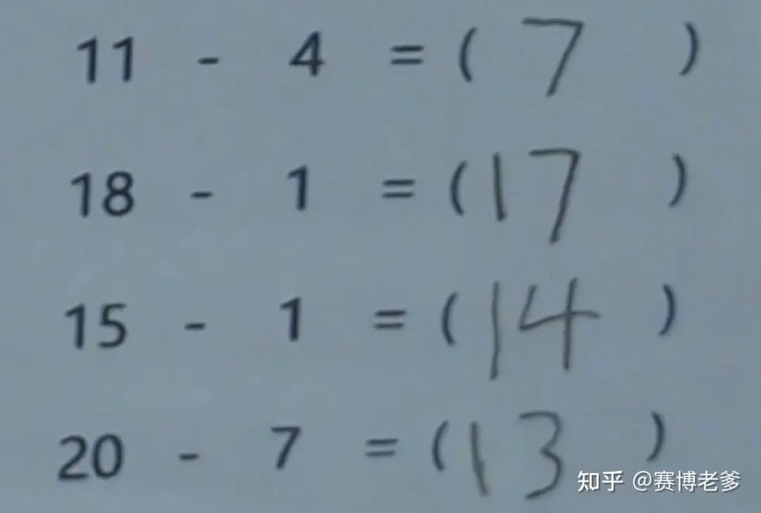
Video resolution is often insufficient to meet this need, as sometimes it is necessary to clearly see small words on the homework or textbooks. Simply increasing the video resolution will increase bandwidth pressure, and real-time transmission of 4K video will make latency unacceptable. According to statistics, if the latency of real-time video communication exceeds 400ms, it will significantly reduce user experience. Therefore, I adopted a mode similar to mobile cameras, defaulting to a low resolution, such as 1k or 2k for real-time preview. When I need to see certain details clearly, I can click a button to take a high-definition 4k photo and transmit it to my local device, allowing me to zoom in indefinitely to see each small word, while in video mode, we aim for latency below 200ms.
Camera Module
After solving the data transmission issue, the focus now shifts to interacting with the Raspberry Pi’s high-definition camera. Our requirements for this camera have been clearly stated: it needs to have two modes: high-definition image mode and smooth video mode. Generally, we will first enter video mode for observation, where the focus is on maintaining video smoothness (frame rate) and real-time performance (latency). At this point, we only need a resolution of 720p or 1080p. However, once we need to look at details on a homework page, we can quickly switch to high-definition photo mode by clicking a shortcut key, allowing the camera to take a high-resolution 4k photo to be displayed on the other end, and it supports saving as a local image for scaling or perspective transformation operations.
For the camera module, we use the <span>libcamera</span> library recommended by Raspberry Pi, which we will encapsulate to provide some APIs:
Camera camera; camera.OpenCamera(); if (video) { camera.ConfigureVideo(); // Configure the camera for video mode, resolution 1080p } else { camera.ConfigureStill(); // Configure the camera for high-definition photo mode, resolution 4k } camera.SetOnFrameCallback([&](const Frame& frame) -> bool { if (video) { video_encoder.Encode(frame.buffer, frame.buffer_size, frame.width, frame.height, frame.stride, frame.timestamp / 1000); // Encode to h264 video format } else { save_frame_to_jpg_file(frame.buffer, frame.buffer_size, frame.width, frame.height, frame.stride, output_file); // Encode to jpg image mode } }); camera.StartCamera(); // ... event loop camera.StopCamera(); camera.Teardown(); camera.CloseCamera();Details of the enlarged high-definition image:
Video Encoding and Decoding Module
For image mode, we directly use <span>libjpeg-turbo</span> to encode a frame of image output from the camera into JPEG format for transmission to the other end.
For video mode, it is slightly more complex. Here we use <span>ffmpeg</span> to encode each frame into h264 video streams, then transmit it to the other end, where it is decoded using <span>ffmpeg</span>’s h264 decoder and displayed on the client screen using <span>SDL2</span>.
We encapsulate the details of video encoding and decoding, providing two interfaces: <span>VideoEncoder</span> and <span>VideoDecoder</span>, as follows:
Video Encoding:
VideoEncoder encoder; encoder.Init(AV_CODEC_ID_H264, width, height,