Due to the changes in the public account article push rules, which no longer sort by publication time, please remember to click the 「Looking」 at the bottom right corner to receive our article pushes on time, and click the “ … ” at the top right corner of the public account homepage to mark Programmer Geek Laboratory as a star so you won’t miss any exciting pushes!

This is a project about motorcycle IoT. As a motorcycle enthusiast, I decided to use my expertise to create a smart dashboard for motorcycles with a Raspberry Pi. It can not only better analyze various data during riding but also improve my riding skills. Doesn’t it look very cool?
Dashboard Features:
-
View the current riding tilt angle.
-
View the current riding acceleration.
-
Monitor oil temperature.
-
Automatically switch to dark mode when riding in dark environments.
-
Record riding data and view personal statistics.
Materials List
-
Raspberry Pi × 1
-
12V-5V USB charger × 1
-
4-pin relay with fuse × 1
-
Breadboard with jumper wires (optional) × 1
-
A set of resistors × 1
-
0.2mm wire × several
-
Breakout Pi plus × 1 (prototype board installed on top of the Raspberry Pi)
-
DS18B20 1 Wire waterproof temperature sensor × 1
-
Oil temperature sensor × 1
-
MPU6050 three-axis gyroscope accelerometer × 1
-
Inclination sensor × 1
-
Acceleration sensor × 1
-
LDR × 1
-
MCP3008 eight-channel ten-bit ADC with SPI interface × 1
-
TFT SPI display × 1
-
RGB LED × 1
-
Plastic box × 1
-
Raspberry Pi case × 1
-
Soldering iron × 1
-
Solder × 1
-
2.5mm screws × several
-
Washers × several
-
Waterproof wire connectors × 1
-
Strong glue × 1
Designing the Circuit


The circuit diagram is shown in the figure. Please follow the PDF instructions to lay out the circuit. If you are not confident, you can install all components of the project on the breadboard for testing. Note to use the 3.3V pin of the Raspberry Pi instead of the 5V pin.
Before powering the Raspberry Pi, please carefully check the circuit to ensure there are no short circuits.
Download the PDF file from the project file library.https://make.quwj.com/project/260
Setting Up the Raspberry Pi

The Raspberry Pi serves as the operating system for the project, mainly responsible for processing angle sensors, storing service pages, running the backend, and managing the database.
Now we will start setting up the Raspberry Pi.
1. Install the Custom Raspbian Image
This image contains the packages required to start the project:
-
Apache for the website frontend.
-
MariaDB database.
-
phpMyAdmin for database operations.
-
Custom permissions to avoid issues.
Download the custom image here:https://drive.google.com/file/d/1wWtb2ZWEqh_-uxrbW7SYPqas-9emT4e-/view?usp=sharing
Once the image is installed, connect the Raspberry Pi to the computer using an Ethernet cable. Then use an SSH client to connect to the IP address 169.254.10.1.
2. Configure Wireless AP
After the above configuration is complete, you can connect to the Raspberry Pi via WiFi, turning it into a wireless AP. Relevant tutorial:https://thepi.io/how-to-use-your-raspberry-pi-as-a-wireless-access-point/
You can follow the tutorial up to step seven. We do not need step eight.
3. Enable Interfaces
Enter raspi-config
sudo raspi-configNavigate to the interface options and enable 1-wire, SPI, and I2C, then restart the Raspberry Pi.
4. Set Up Display Driver
Initialize the display by editing the file name: /etc/modules
sudo nano /etc/modulesAdd the following two lines
spi-bcm2835
fbtft_device
Edit /etc/modprobe.d/fbtft.conf
sudo nano /etc/modprobe.d/fbtft.confAdd the following line
options fbtft_device name=tm022hdh26 gpios=reset:25,dc:24,led:18 rotate=90 speed=80000000 fps=60Restart the Raspberry Pi. If you see the light on the back of the display turn on, everything is normal. The display will initialize every time the Raspberry Pi starts, but it will only show a black screen now.
If you want to display the content of the Raspberry Pi on the screen, we need to copy the content of the main screen to the small LCD. We call it the ‘fbcp’ service.
Install fbcp Service
sudo apt-get install cmake
git clone   https://github.com/tasanakorn/rpi-fbcp
cd rpi-fbcp
mkdir build
cd build/
cmake ..
make
sudo install fbcp /usr/local/bin/fbcp
Now, the service is installed. However, since we are only using the Raspberry Pi without a display, to output the screen content on the Raspberry Pi, edit /boot/config.txt
sudo nano /boot/config.txtFind and uncomment or add the following lines in this file:
hdmi_force_hotplug=1
hdmi_cvt=640 480 60 0 0 0 0
display_rotate=0
hdmi_group=2
hdmi_mode=87
Restart the Raspberry Pi and enter fbcp in the console to test the fbcp service. Now you can see the content on the LCD.
Run fbcp on Startup
Edit /etc/rc.local and add the following line between the IP address and exit line
fbcp &Once set, the display will turn on every time the Raspberry Pi starts.
Designing the Database
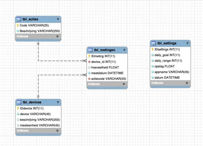
To record and store angle sensors, I designed my own database. As shown in the figure, it contains four tables.
1. Device Section
This table includes each sensor, including sensor name, description, and measurement unit. This table has a one-to-many relationship with the operation table, where the acceleration sensor can perform different tasks in this project.
2. Action Section
This table can store actions of different sensors. Ensure that an action is always associated with a specific sensor. For example: the action ‘TEMP’ is connected to the device that measures temperature. This would be the 1-wire temperature sensor.
3. History
This table contains records of all sensors. Each record includes an action ID, a value, a timestamp, and a riding ID.
4. Riding Section
This table stores different riding routes. Each time the user rides again, it will be re-entered in this table.
You can obtain this database on the Raspberry Pi by copying it from my GitHub repository. In the database folder, you will find two .sql files.
Run them in PhpMyAdmin or MySQL Workbench. After that, the database should be on your Raspberry Pi.https://github.com/EveraertAlexander/motoDash
Backend
If you haven’t copied the repository from my GitHub yet, you can find the complete backend of the project in the Backend folder.
In the directory under /helpers, read the categories of sensors, which are used in the files under /repositories to communicate with the database, and the main application is located in a file named app.py in the root directory.
Install Python Packages
Before running the program, we need to install some packages for Python. Enter the terminal of the Raspberry Pi and input the following commands:
pip3 install mysql-connector-python
pip3 install flask-socketio
pip3 install flask-cors
pip3 install gevent
pip3 install gevent-websocket
Note: If you change the password of MariaDB/MySQL, please change the password in config.py.
Test the Backend
Run app.py using the python3 interpreter (/usr/bin/python3). Ensure there are no errors.
Run Backend on Startup
Edit motoDash_backend.service and modify YOURFILEPATH to the path of the storage folder.
Copy this file to /etc/systemd/system/
sudo cp motoDash_backend.service /etc/systemd/system/motoDash_backend.service.Now, the backend will automatically start every time the Raspberry Pi boots up.
Frontend

Enter the GitHub Repo. Copy the contents of the Frontend directory to /var/www/html.
This is all the work needed for the frontend. This folder contains all the web pages, styles, and scripts for the web interface. It can also communicate with the backend.
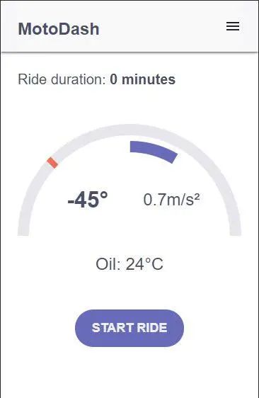
After testing everything is running correctly, connect to the Raspberry Pi and enter the IP address of the Raspberry Pi in your browser. You will reach the homepage of the web interface.
Note: This page is responsive, so you can use it on mobile devices as well as desktops.
Display Dashboard on the Monitor

The frontend has hidden web pages designed for small displays. We will open this website in full-screen mode when the Raspberry Pi starts automatically.
Ensure that the Raspberry Pi is set to desktop auto-login in the boot options under raspi-config.
sudo raspi-configNow enter the hidden configuration folder and create a new file in it.
cd .config
sudo mkdir -p lxsession/LXDE-pi
sudo nano lxsession/LXDE-pi/autostart
Add the following lines to this file and save.
@xscreensaver -no-splash
@xset s off
@xset -dpms
@xset s noblank
@chromium-browser --noerrors --disable-session-crashed-bubble --disable-infobars --kiosk --incognito  http://127.0.0.1/dashboard_main.html
Now, every time the Raspberry Pi starts, this webpage will be displayed.
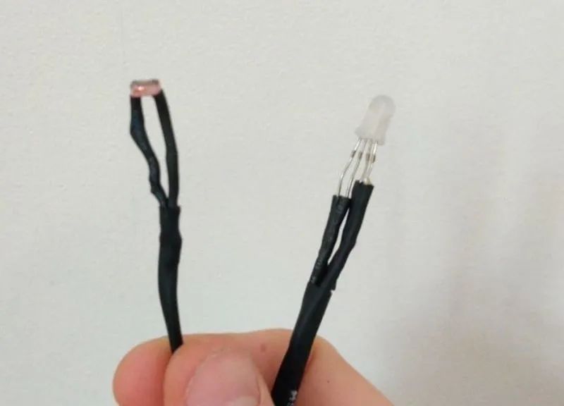
Soldering Electronic Components

Solder according to the component structure, connecting the sensors and modules to the correct pins. Make sure to solder the pins correctly.

Soldering Tips:
-
When soldering over a long distance, use insulated wires.
-
After soldering components or wires, use a multimeter to check for connectivity. Also, regularly check for short circuits in the circuit.
-
Do not use too much or too little solder.
-
If you are unsure how to solder, practice on another prototype board.
Ensure that the wires soldered to the sensors are long enough, and use heat shrink tubing to prevent short circuits.
After all soldering is completed, carefully check for short circuits or poor connections, and ensure that the electronic components are soldered correctly according to the design.

Once everything works properly, install the breakout board on the Raspberry Pi and secure it with 2.5mm screws and standoffs, then correctly install the sensors and test on the website.
Power Supply
I use a 12V-5V USB adapter to power the Raspberry Pi. This adapter will connect to the motorcycle battery. We use a relay to ensure that the Raspberry Pi is powered on when the ignition switch is turned on. When the relay detects the tail light voltage, it will turn off the power circuit of the Raspberry Pi (the tail light is always on when the ignition is on).
For more detailed tutorials, please click the link below:https://www.hondagrom.net/threads/2017-gromsf-msx125sf-wire-up-auxiliary-power-for-pcv-wb2-and-other-fuel-controllers.16921/
Enclosure


Display Enclosure
The display uses a hard plastic box. The size can match the display, and be sure to drill two holes in the front for the RGB LED and LDR. I used bolts to mount this box on top of the smartphone holder.

Temperature Sensor Enclosure
3D print an enclosure that matches the size of my motorcycle fuel gauge.

Raspberry Pi Enclosure
Install the Raspberry Pi in a safe location inside the motorcycle. I used some Velcro straps to secure it under one of the fenders and protected it with a case and some plastic to prevent damage to the components.

Accelerometer
Install the accelerometer in a safe place, preferably mounted on the motorcycle frame.
You can choose the enclosure for the electronic components freely. Just ensure that the electronic components are waterproof and dustproof.
This project file library address:
http://make.quwj.com/project/260
via instructables.com/id/Raspberry-Pi-Motorcycle-Dashboard/
Recommended Reading: (Click the title to jump)
How to Find the Exact Location of the Photographer Through a Photo

Likes and views are the greatest support
