Follow+Star Public Number, don’t miss exciting content

Source | Renesas Embedded Encyclopedia
CAN has a wide range of applications, and many microcontrollers now integrate CAN controllers internally. Today, I will describe its application case in conjunction with the CAN controller module of the Renesas RA2 microcontroller.
Introduction to Renesas RA2L1 Series MCU
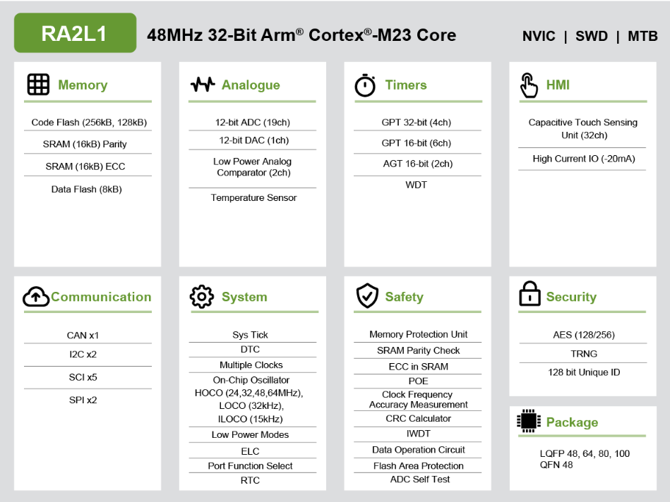
The RA2L1 product group is based on the Arm® Cortex®-M23 core (the lowest power CPU in the current Arm® Cortex-M series). This product uses optimized processes and Renesas’ low-power technology, making it a world-class ultra-low power microcontroller. The RA2L1 product group supports a wide voltage operation from 1.6V to 5.5V, with a maximum CPU clock frequency of 48MHz, and even lower operating and standby current. The RA2L1 product family is equipped with an enhanced capacitive touch sensing unit (CTSU2), CAN controller local area network bus, serial communication interface, high-precision analog circuits, and timers. Product packages range from 48 pins to 100 pins.
1
Introduction to Controller Area Network (CAN) Module
The Controller Area Network (CAN) module uses a message-based protocol to receive and transmit data between multiple slaves and masters in electromagnetic noise applications.
This module complies with the ISO11898-1 (CAN2.0A / CAN2.0B) standard, supports up to 32 mailboxes, and can be configured as normal mailboxes and in FIFO mode for sending or receiving. It supports both standard (11-bit) and extended (29-bit) message formats. The CAN module requires an external CAN transceiver.
CAN Module Block Diagram
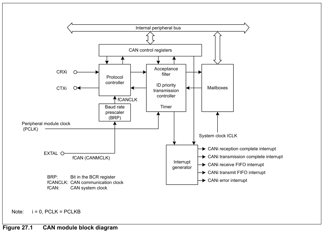
Precautions:
CAN requires an external high-speed crystal as the clock source, and the external high-speed clock must be configured before using the CAN module.
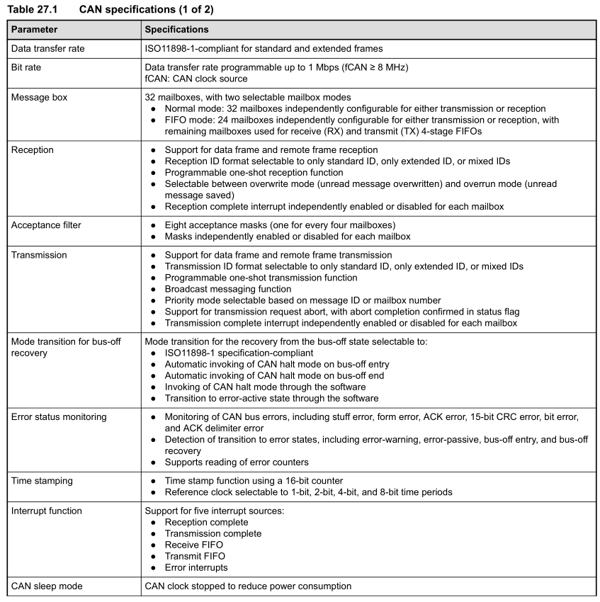
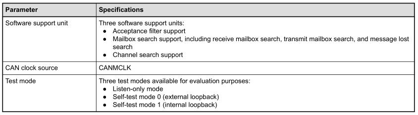
CAN Module Parameter Specifications
2
RA2L1 CAN Communication Application Example
Create an RA2L1 project using the official e2 studio development tool and add the CAN peripheral module’s underlying application.
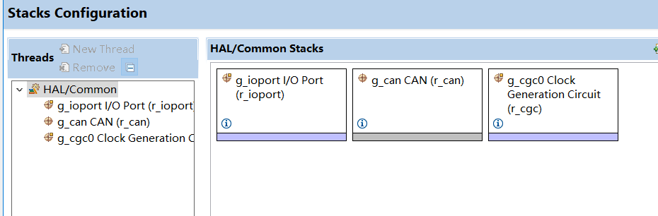
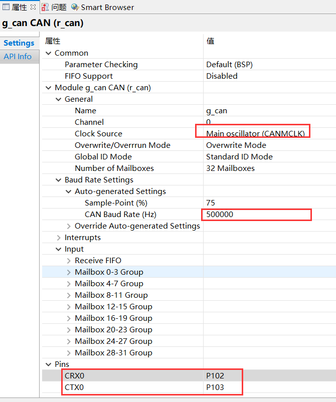
Configure CAN module parameters (including communication rate, pin configuration, etc.).
3
CAN Application Reference Code
Swipe left and right to view the full content
#define WAIT_TIME                       (500U)             //wait time value
#define CAN_MAILBOX_NUMBER_TX           (0U)               //mail box number
#define CAN_MAILBOX_NUMBER_RX           (1U)
#define CAN_FRAME_TRANSMIT_DATA_BYTES   (8U)               //data length
#define ZERO                            (0U)
/* Private global variables*/
/* Flags, set from Callback function */
static volatile bool b_can_tx = false;                  //CAN transmission status
static volatile bool b_can_rx = false;                  //CAN receive status
static volatile bool b_can_err = false;                 //CAN error status
/* CAN frames for tx and rx */
static can_frame_t g_can_tx_frame;                      //CAN transmit frame
static can_frame_t g_can_rx_frame;                      //CAN receive frame

void hal_entry(void){    /* TODO: add your own code here */    fsp_err_t err = FSP_SUCCESS;    uint32_t time_out = WAIT_TIME;                                      // time out    uint8_t can_tx_msg[CAN_FRAME_TRANSMIT_DATA_BYTES] = {0,1,2,3,4,5,6,7};    uint8_t can_rx_msg[CAN_FRAME_TRANSMIT_DATA_BYTES] = {0};    /* Initializes the CGC module. */    err = R_CGC_Open(&g_cgc0_ctrl, &g_cgc0_cfg);    /* Handle any errors. This function should be defined by the user. */    assert(FSP_SUCCESS == err);
    /* Start the CGC_CLOCK_MAIN_OSC. */    err = R_CGC_ClockStart(&g_cgc0_ctrl, CGC_CLOCK_MAIN_OSC, NULL);    assert(FSP_SUCCESS == err);
    /* Initialize CAN module */    err = R_CAN_Open(&g_can_ctrl, &g_can_cfg);    /* Error trap */    if(FSP_SUCCESS != err)    {        __asm("BKPT #0\n");    }    g_can_tx_frame.id = CAN_MAILBOX_NUMBER_TX;    g_can_tx_frame.type = CAN_FRAME_TYPE_DATA;    g_can_tx_frame.data_length_code = CAN_FRAME_TRANSMIT_DATA_BYTES;
    /* copy the tx data frame with TX_MSG */    memcpy((uint8_t*)&g_can_tx_frame.data[ZERO], (uint8_t*)&can_tx_msg[ZERO], CAN_FRAME_TRANSMIT_DATA_BYTES);    err = R_CAN_Write(&g_can_ctrl, CAN_MAILBOX_NUMBER_TX, &g_can_tx_frame);    /* Error trap */    if (FSP_SUCCESS != err)    {        err = R_CAN_Close(&g_can_ctrl);        if (FSP_SUCCESS != err)        {            __asm("BKPT #0\n");        }    }
    while(1)    {        /* check if receive flag is set */        if (true == b_can_rx)        {            /* Reset flag bit */            b_can_rx = false;
            g_can_rx_frame.data[CAN_FRAME_TRANSMIT_DATA_BYTES-1] = g_can_rx_frame.id;
            /* Transmit the rx data frame as acknowledging the data transfer is successful */            err = R_CAN_Write (&g_can_ctrl, CAN_MAILBOX_NUMBER_TX, &g_can_rx_frame);            /* Error trap */            if (FSP_SUCCESS != err)            {                err = R_CAN_Close(&g_can_ctrl);                if (FSP_SUCCESS != err)                {                    __asm("BKPT #0\n");                }            }            /* wait for transmit flag bit to set */            while ((true != b_can_tx) && (time_out--));            if (0 == time_out)            {                __asm("BKPT #0\n");            }            /* Reset flag bit */            b_can_tx = false;        }    }}

void can_callback(can_callback_args_t *p_args){    switch (p_args->event)    {        case CAN_EVENT_TX_COMPLETE:        {            b_can_tx = true;        //set flag bit            break;        }
        case CAN_EVENT_RX_COMPLETE:        {            b_can_rx = true;//copy the received data to rx_frame    memcpy(&g_can_rx_frame, p_args->p_frame, sizeof(can_frame_t));              break;        }
        case CAN_EVENT_MAILBOX_MESSAGE_LOST:    //overwrite/overrun error event        case CAN_EVENT_BUS_RECOVERY:            //Bus recovery error event        case CAN_EVENT_ERR_BUS_OFF:             //error Bus Off event        case CAN_EVENT_ERR_PASSIVE:             //error passive event        case CAN_EVENT_ERR_WARNING:             //error warning event        {            b_can_err = true;                   //set flag bit            break;        }    }}
4
Validation of CAN Communication
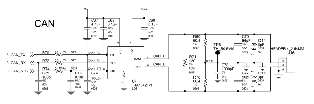
The RA2L1 chip only has a CAN controller internally, and when communicating with external CAN devices, an external CAN transceiver is also required.
CAN Transceiver Application Reference Schematic
Use USB-CAN tools to test CAN communication
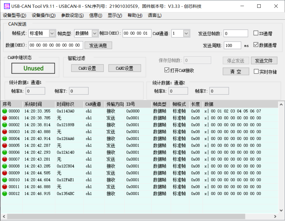
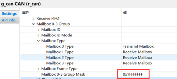
a. Unable to receive data with ID 0
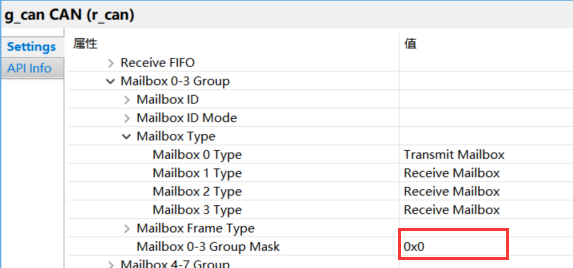
b. After disabling Mask function, all ID data can be received.
How to implement effective code protection measures during MCU product testing and operation
MCU High-Precision Rotary Transformer Motor Control Solution
Process of Porting AI Models in MPU